OXCB950
OXFORD SEMICONDUCTOR LTD.
2
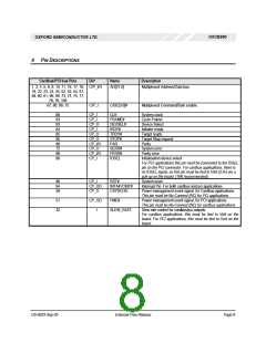
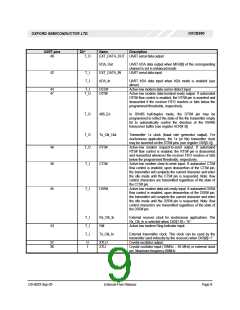
UART pins
Dir
Name
Description
49
T_O
EXT_DATA_OUT UART serial data output
IrDA_Out
UART IrDA data output when MCR[6] of the corresponding
channel is set in enhanced mode
42
T_I
T_I
EXT_DATA_IN
IrDA_In
UART serial data input
UART IrDA data input when IrDA mode is enabled (see
above)
44
47
T_I
DCD#
DTR#
Active-low modem data-carrier-detect input
Active-low modem data-terminal-ready output. If automated
DTR# flow control is enabled, the DTR# pin is asserted and
deasserted if the receiver FIFO reaches or falls below the
programmed thresholds, respectively.
T_O
T_O
485_En
In RS485 half-duplex mode, the DTR# pin may be
programmed to reflect the state of the the transmitter empty
bit to automatically control the direction of the RS485
transceiver buffer (see register ACR[4:3])
T_O
T_O
Tx_Clk_Out
RTS#
Transmitter 1x clock (baud rate generator output). For
isochronous applications, the 1x (or Nx) transmitter clock
may be asserted on the DTR# pins (see register CKS[5:4])
Active-low modem request-to-send output. If automated
RTS# flow control is enabled, the RTS# pin is deasserted
and reasserted whenever the receiver FIFO reaches or falls
below the programmed thresholds, respectively.
48
46
T_I
T_I
CTS#
DSR#
Active-low modem clear-to-send input. If automated CTS#
flow control is enabled, upon deassertion of the CTS# pin,
the transmitter will complete the current character and enter
the idle mode until the CTS# pin is reasserted. Note: flow
control characters are transmitted regardless of the state of
the CTS# pin.
45
Active-low modem data-set-ready input. If automated DSR#
flow control is enabled, upon deassertion of the DSR# pin,
the transmitter will complete the current character and enter
the idle mode until the DSR# pin is reasserted. Note: flow
control characters are transmitted regardless of the state of
the DSR# pin
T_I
T_I
T_I
Rx_Clk_In
RI#
External receiver clock for isochronous applications. The
Rx_Clk_In is selected when CKS[1:0] = ‘01’.
Active-low modem Ring-Indicator input
43
Tx_Clk_In
External transmitter clock. This clock can be used by the
transmitter (and indirectly by the receiver) when CKS[6]=’1’.
Crystal oscillator output
37
36
O
I
XTLO
XTLI
Crystal oscillator input (10MHz – 40 MHz) or external clock
pin. Maximum frequency 60MHz
DS-0033 Sep 05
External-Free Release
Page 9

 OXFORD [ OXFORD SEMICONDUCTOR ]