Page No. : 6/10
Inductor Core Selection
The inductor type must be selected once the value for L is known. Generally speaking, high efficiency converters can not
afford the core loss found in low cost powdered iron cores. So, the more expensive ferrite or mollypermalloy cores will be a
better choice.
The selected inductance rather than the core size for a fixed inductor value is the key for actual core loss. As the inductance
increases, core losses decrease. Unfortunately, increase of the inductance requires more turns of wire and therefore the
copper losses will increase.
Ferrite designs are preferred at high switching frequency due to the characteristics of very low core losses. So, design goals
can focus on the reduction of copper loss and the saturation prevention.
Ferrite core material saturates “hard”, which means that inductance collapses abruptly when the peak design current is
exceeded. The previous situation results in an abrupt increase in inductor ripple current and consequent output voltage
ripple.
Do not allow the core to saturate! Different core materials and shapes will change the size/ current and price/current
relationship of an inductor.
Toroid or shielded pot cores in ferrite or permalloy materials are small and do not radiate energy. However, they are usually
more expensive than the similar powdered iron inductors. The rule for inductor choice mainly depends on the price vs. size
requirement and any radiated field/EMI requirements.
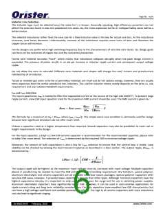
CIN and COUT Selection
The input capacitance, CIN, is needed to filter the trapezoidal current at the source of the high side MOSFET. To prevent large
ripple current, a low ESR input capacitor sized for the maximum RMS current should be used. The RMS current is given by:
VOUT
VIN
VIN
VOUT
IRMS = IOUT (MAX ) ⋅
⋅
− 1
This formula has a maximum at VIN = 2VOUT, where IRMS = IOUT/2. This simple worst‐case condition is commonly used for design
because even significant deviations do not offer much relief.
Choose a capacitor rated at a higher temperature than required. Several capacitors may also be paralleled to meet size or
height requirements in the design.
For the input capacitor, a 10μF x 2 low ESR ceramic capacitor is recommended. For the recommended capacitor, please refer
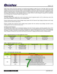
to table 3 for more detail. The selection of COUT is determined by the required ESR to minimize voltage ripple.
Moreover, the amount of bulk capacitance is also a key for COUT selection to ensure that the control loop is stable. Loop
stability can be checked by viewing the load transient response as described in a later section. The output ripple, ΔVOUT , is
determined by:
1
⎡
⎤
ΔVOUT ≤ ΔIL ⋅ ESR +
⎢
⎥
8 fCOUT
⎣
⎦
The output ripple will be highest at the maximum input voltage since ΔIL increases with input voltage. Multiple capacitors
placed in parallel may be needed to meet the ESR and RMS current handling requirement. Dry tantalum, special polymer,
aluminum electrolytic and ceramic capacitors are all available in surface mount packages. Special polymer capacitors offer
very low ESR value. However, it provides lower capacitance density than other types. Although Tantalum capacitors have the
highest capacitance density, it is important to only use types that pass the surge test for use in switching power supplies.
Aluminum electrolytic capacitors have significantly higher ESR. However, it can be used in cost‐sensitive applications for
ripple current rating and long term reliability considerations. Ceramic capacitors have excellent low ESR characteristics but
can have a high voltage coefficient and audible piezoelectric effects. The high Q of ceramic capacitors with trace inductance
can also lead to significant ringing.
DS‐RS6519‐05 February, 2010
www.Orister.com

 ORISTER [ ORISTER CORPORATION ]