NGTG12N60TF1G
Continued from preceding page.
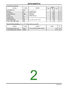
Ratings
typ
Parameter
Symbol
Conditions
Unit
min
max
Turn-ON Delay Time
Rise Time
t (on)
55
ns
ns
ns
ns
ns
ns
nC
nC
nC
d
V
=300V,I =15A
C
=30Ω,L=200μH
CC
t
30
r
R
G
Turn-ON Time
ton
t (off)
330
200
110
350
84
V
GE
=0V/15V
Turn-OFF Delay Time
Fall Time
d
Vclamp=400V
t
f
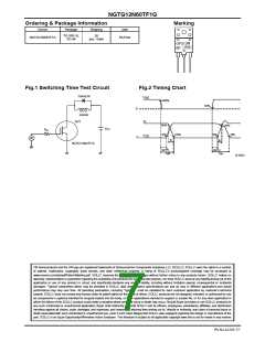
See Fig.1, See Fig.2
Turn-OFF Time
toff
Total Gate Charge
Gate to Emitter Charge
Gate to Collector “Miller” Charge
Qg
Qge
Qgc
V
CE
=300V, V =15V, I =15A
GE
16
C
37
Thermal Characteristics at Ta = 25°C, Unless otherwise specified
Parameter
Symbol
Conditions
Ratings
Unit
Thermal Resistance (junction- Case)
Rth(j-c)
Rth(j-a)
Tc=25
°
C (our ideal heat dissipation condition)*2
2.33
47.5
°C /W
°C /W
Thermal Resistance (junction- atmosphere)
No.A2219-2/7

 ONSEMI [ ONSEMI ]