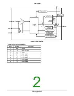
NCV8461
Table 3. ELECTRICAL CHARACTERISTICS (V = 13.5 V; −40°C < T < 150°C unless otherwise specified)
D
J
Value
Typ
Min
Max
Rating
Symbol
Conditions
Unit
PROTECTION FUNCTIONS (Note 4)
Repetitive Short Circuit Current
Limit
I
T = T (Note 3)
1
A
V
lim(SC)
J
Jt
Switch Off Output Clamp
Voltage
V
I
= 4 mA, V = 0 V
V
−
V
−
clamp
D
in
D
D
47
41
DIAGNOSTICS CHARACTERISTICS
Short Circuit Detection Voltage
V
2.8
V
V
OUT(SC)
Openload Off State Detection
Threshold
V
OL
V
in
= 0 V
1.5
3.5
Openload Detection Current
I
5
mA
L(OL)
3. Not subjected to production testing
4. To ensure long term reliability under heavy overload or short circuit conditions, protection and related diagnostic signals must be used
together with a proper hardware/software strategy. If the devices operates under abnormal conditions this hardware/software solutions
must limit the duration and number of activation cycles.
Table 4. STATUS PIN TRUTH TABLE
Conditions
Normal Operation
Input
Output
Status
L
H
L
H
H
H
Short Circuit to GND
L
H
L
L*
H
L
Short to V
L
H
H
H
L
H
D (OFF State)
Current Limitation
Overtemperature
L
H
L
H**
H
H
L
H
L
L
H
L
OFF State Open Load
L
H
H
H
L
H
* Output = “L”; V
< 2 V typ.
OUT
OUT
** Output = “H”; V
> 2 V typ.
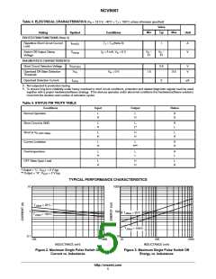
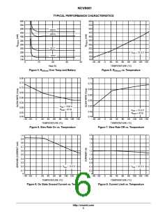
TYPICAL PERFORMANCE CHARACTERISTICS
10
1000
T
JStart
= 25°C
1
100
T
JStart
= 25°C
T
JStart
= 150°C
T
JStart
= 150°C
0.1
10
100
1000
10
100
1000
INDUCTANCE (mH)
INDUCTANCE (mH)
Figure 2. Maximum Single Pulse Switch Off
Current vs. Inductance
Figure 3. Maximum Single Pulse Switch Off
Energy vs. Inductance
http://onsemi.com
5

 ONSEMI [ ONSEMI ]