NCP1406
switches on, the capacitor C1 is effectively connected like
a reversed battery and C1 discharges the stored charge
through the R of the internal MOSFET and D3 to
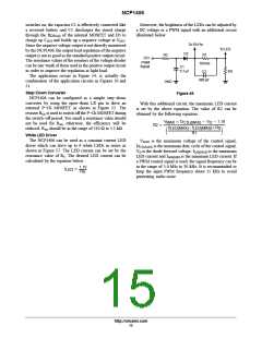
Moreover, the brightness of the LEDs can be adjusted by
a DC voltage or a PWM signal with an additional circuit
illustrated below:
DS(on)
charge up COUT and builds up a negative voltage at VOUT
.
To FB Pin
To LED
D2
Since the negative voltage output is not directly monitored
by the NCP1406, the output load regulation of the negative
output is not as good as the standard positive output circuit.
The resistance values of the resistors of the voltage divider
can be one−tenth of those used in the positive output circuit
in order to improve the regulation at light load.
The application circuit in Figure 54, is actually the
combination of the application circuits in Figures 50 and
51.
R2
R1
100 kW
C2
DC/
PWM
Signal
C1
0.1 mF
RS
680 pF
GND
Step−Down Converter
Figure 45.
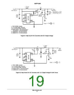
NCP1406 can be configured as a simple step−down
converter by using the open−drain LX pin to drive an
external P−Ch MOSFET as shown in Figure 52. The
resistor RGS is used to switch off the P−Ch MOSFET during
the switch−off period. Too small a resistance value should
not be used for RGS, otherwise, the efficiency will be
reduced. RGS should be in the range of 510 W to 5.1 kW.
With this additional circuit, the maximum LED current
is set by the above equation. The value of R2 can be
obtained by the following equation:
V
D * V * 1.19
CTL(MAX) D
MAX
(I
R2 +
*I
) R
S
LED(MAX) LED(MIN)
R1
ǒ
Ǔ
White LED Driver
The NCP1406 can be used as a constant current LED
driver which can drive up to 6 white LEDs in series as
shown in Figure 57. The LED current can be set by the
resistance value of RS. The desired LED current can be
calculated by the equation below:
VMAX is the maximum voltage of the control signal,
DCTL(MAX) is the maximum duty cycle of the control signal,
VD is the diode forward voltage, ILED(MAX) is the maximum
LED current and ILED(MIN) is the minimum LED current. If
a PWM control signal is used, the signal frequency can be
in the range of 5.0 kHz to 30 kHz. It is recommended to
keep the input PWM frequency about 15 kHz to avoid
generating audio noise.
1.19
I
+
LED
R
S
http://onsemi.com
15

 ONSEMI [ ONSEMI ]