NCP1399AA, NCP1399BA, NCP1399AC
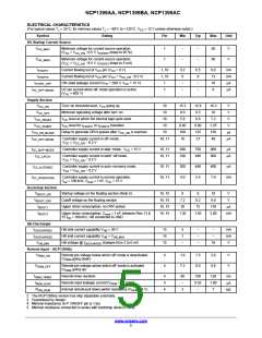
ELECTRICAL CHARACTERISTICS
(For typical values T = 25°C, for min/max values T = −40°C to +125°C, V = 12 V unless otherwise noted.)
J
J
CC
Symbol
OVP/OTP
Rating
Pin
Min
Typ
Max
Unit
I
OTP/OVP pin source current for external NTC –
during normal operation
7
7
90
95
100
200
mA
mA
OTP
I
OTP/OVP pin source current for external NTC –
during startup
180
190
OTP_BOOST
t
Internal filter for OVP comparator
Internal filter for OTP comparator
7
7
7
32
200
7.3
37
330
8.0
44
500
8.7
ms
ms
OVP_FILTER
t
OTP_FILTER
t
Blanking time for OTP input during startup (NCP1399AA,
NCP1399BA)
ms
BLANK_OTP
Blanking time for OTP input during startup (NCP1399AC)
7
7
7
14
1.0
1.8
16
1.2
2.4
18
1.4
3.0
ms
V
V
OVP/OTP pin clamping voltage @ I
OVP/OTP pin clamping voltage @ I
= 0 mA
= 1 mA
CLAMP_OVP/OTP_1
OVP/OTP
OVP/OTP
V
V
CLAMP_ OVP/OTP_2
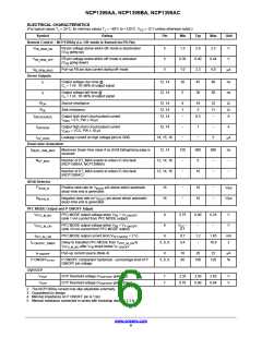
Start−up Sequence Parameters
t
Maximum on−time clamp (NCP1399AA, NCP1399BA)
Maximum on−time clamp (NCP1399AC)
Initial Mlower DRV on−time duration
12, 14
12, 14
12
7.3
10.6
4.7
0.72
17
7.7
11.2
4.9
0.79
20
8.4
12.1
5.4
0.88
22
ms
ms
ms
ms
ns
−
TON_MAX
t
1st_MLOWER_TON
t
Initial Mupper DRV on−time duration
14
1st_MUPPER_TON
t
On−time period increment during soft−start
12, 14
12, 14
SS_INCREMENT
K
Soft−Start increment division ratio (NCP1399AA,
NCP1399BA)
−
4
−
SS_INCREMENT
Soft−Start increment division ratio (NCP1399AC)
12, 14
12, 14
−
8
−
−
t
Time duration to restart IC if start−up phase is not finished
0.45
0.50
0.55
ms
WATCHDOG
Feedback Section
R
Internal pull−up resistor on FB pin
5
5
5
5
15
18
25
kW
−
FB
FB
K
V
FB
to internal current set point division ratio
1.92
4.60
4.4
2.00
4.95
4.6
2.08
5.30
4.8
V
Internal voltage reference on the FB pin
V
FB_REF
V
Internal clamp on FB input of On−time comparator referred
to external FB pin voltage
V
FB_CLAMP
V
Feedback voltage thresholds to enters in skip mode for
NCP1399By version (Note 2)
5
0.44
0.50
0.56
V
FB_SKIP_IN
V
Skip comparator hysteresis
5
130
160
200
mV
FB_SKIP_HYST
st
t
On−time duration of 1 Mlower pulse when FB cross
5, 12
0.95
1.05
1.15
ms
1st_MLOWER_SKIP
V
+ V
threshold (NCP1399AA,
FB_SKIP_IN
FB_SKIP_HYST
NCP1399BA)
st
On−time duration of 1 Mlower pulse when FB cross
5, 12
1.8
−
1.9
2.1
−
ms
V
+ V
threshold (NCP1399AC)
FB_SKIP_IN
FB_SKIP_HYST
st
V
Internal FB level reduction during 1 Mupper pulse when FB
5, 6, 14
150
mV
1st_MUPPER_SKIP
cross V
+ V
threshold (Note 3)
FB_SKIP_IN
FB_SKIP_HYST
Skip Input – NCP1399Ay version
Internal Skip pin current source
I
4
4
48
−
50
−
52
10
mA
SKIP
C
Maximum loading capacitance for skip pin voltage filtering
(Note 3)
nF
SKIP_LOAD_MAX
2. The NCP1399Ay version has skip adjustable externally.
3. Guaranteed by design.
4. Minimal impedance on P ON/OFF pin is 1 kW
5. Minimal resistance connected in series with bootstrap diode is 3.3 W
www.onsemi.com
7

 ONSEMI [ ONSEMI ]