NCP1050, NCP1051, NCP1052, NCP1053, NCP1054, NCP1055
50
46
42
38
1.39
1.38
CURRENT RISING
1.37
1.36
1.35
1.34
I
= 25 m A
1.33
1.32
1.31
1.30
SINK
CURRENT FALLING
34
30
1.29
1.28
−50 −25
0
25
50
75
100
125 150
−50 −25
0
25
50
75
100
125 150
TEMPERATURE (°C)
TEMPERATURE (°C)
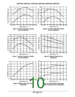
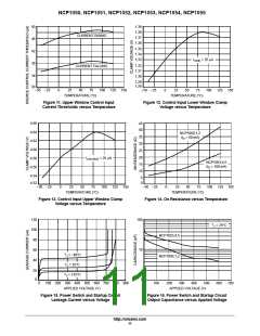
Figure 11. Upper Window Control Input
Current Thresholds versus Temperature
Figure 12. Control Input Lower Window Clamp
Voltage versus Temperature
4.66
4.64
4.62
4.60
4.58
4.56
45
40
NCP1050,1,2
(I = 50 mA)
D
35
30
25
20
15
10
I
= 25 m A
SOURCE
NCP1053,4,5
(I = 100 mA)
D
4.54
4.52
5
0
−50 −25
0
25
50
75
100
125 150
−50 −25
0
25
50
75
100 125 150
TEMPERATURE (°C)
TEMPERATURE (°C)
Figure 13. Control Input Upper Window Clamp
Voltage versus Temperature
Figure 14. On Resistance versus Temperature
120
100
80
100
10
1
T = 25°C
J
NCP1053,4,5
NCP1050,1,2
60
T = −40°C
J
40
T = 25°C
J
20
0
T = 125°C
J
0
100 200 300 400 500 600 700 800 900
APPLIED VOLTAGE (V)
0
100
200
300
400
500
600
700
APPLIED VOLTAGE (V)
Figure 15. Power Switch and Startup Circuit
Leakage Current versus Voltage
Figure 16. Power Switch and Startup Circuit
Output Capacitance versus Applied Voltage
http://onsemi.com
11

 ONSEMI [ ONSEMI ]