NCP1050, NCP1051, NCP1052, NCP1053, NCP1054, NCP1055
OPERATING DESCRIPTION
Introduction
followers at approximately 47.5 m A with 10 m A hysteresis.
When a source or sink current in excess of this value is
applied to this input, a logic signal generated internally
changes state to block power switch conduction. Since the
output of the Control Input sense is sampled continuously
The NCP105X series represents a new higher level of
integration by providing on a single monolithic chip all of
the active power, control, logic, and protection circuitry
required to implement a high voltage flyback converter and
compliance with very low standby power requirements for
modern consumer electronic power supplies. This device
series is designed for direct operation from a rectified 240
VAC line source and requires minimal external components
for a complete cost sensitive converter solution. Potential
markets include cellular phone chargers, standby power
supplies for personal computers, secondary bias supplies for
microprocessor keep−alive supplies and IR detectors. A
description of each of the functional blocks is given below,
and the representative block diagram is shown in Figure 2.
This device series features an active startup regulator
circuit that eliminates the need for an auxiliary bias winding
on the converter transformer, fault logic with a programmable
timer for converter overload protection, unique gated
oscillator configuration for extremely fast loop response with
double pulse suppression, oscillator frequency dithering with
during t (77% duty cycle), it is possible to turn the Power
on
Switch Circuit on or off at any time within t . Because it
on
does not have to wait for the next cycle (rising edge of the
clock signal) to switch on, and because it does not have to
wait for current limit to turn off, the circuit has a very fast
transient response as shown in Figure 3.
In a typical converter application the control input current
is drawn by an optocoupler. The collector of the optocoupler
is connected to the Control Input pin and the emitter is
connected to ground. The optocoupler LED is mounted in
series with a shunt regulator (typically a TL431) at the DC
output of the converter. When the power supply output is
greater than the reference voltage (shunt regulator voltage
plus optocoupler diode voltage drop), the optocoupler turns
on, pulling down on the Control Input. The control input
logic is configured for line input sensing as well.
a
controlled slew rate driver for reduced EMI,
Turn On Latch
cycle−by−cycle current limiting, input undervoltage lockout
with hysteresis, thermal shutdown, and auto restart or latched
off fault detect device options. These devices are available in
economical 8−pin PDIP and 4−pin SOT−223 packages.
The Oscillator output is typically a 77% positive duty
cycle square waveform. This waveform is inverted and
applied to the reset input of the turn−on latch to prevent any
power switch conduction during the guaranteed off time.
This square wave is also gated by the output of the control
section and applied to the set input of the same latch.
Because of this gating action, the power switch can be
activated when the control input is not asserted and the
oscillator output is high.
The use of this unique gated Turn On Latch over an
ordinary Gated Oscillator allows a faster load transient
response. The power switch is allowed to turn on
immediately, within the maximum duty cycle time period,
when the control input signals a necessary change in state.
Oscillator
The Oscillator is a unique fixed−frequency, duty−cycle−
controlled oscillator. It charges and discharges an on chip
timing capacitor to generate a precise square wave signal
used to pulse width modulate the Power Switch Circuit.
During the discharge of the timing capacitor, the Oscillator
duty cycle output holds one input of the Driver low. This
action keeps the Power Switch Circuit off, thus limiting the
maximum duty cycle.
A frequency modulation feature is incorporated into the
IC in order to aide in EMI reduction. Figure 3 illustrates this
frequency modulation feature. The power supply voltage,
Turn Off Latch
A Turn Off Latch feature has been incorporated into this
device series to protect the power switch circuit from
excessive current, and to reduce the possibility of output
overshoot in reaction to a sudden load removal. If the Power
Switch current reaches the specified maximum current limit,
the Current Limit Comparator resets the Turn Off Latch and
turns the Power Switch Circuit off. The turn off latch is also
reset when the Oscillator output signal goes low or the
Control Input is asserted, thus terminating output MOSFET
conduction. Because of this response to control input
signals, it provides a very fast transient response and very
tight load regulation. The turn off latch has an edge triggered
set input which ensures that the switch can only be activated
once during any oscillator period. This is commonly
referred to as double pulse suppression.
V
, acts as the input to the built−in voltage controlled
CC
oscillator. As the V voltage is swept across its nominal
operating range of 7.5 to 8.5 V, the oscillator frequency is
swept across its corresponding range.
CC
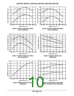
The center oscillator frequency is internally programmed
for 44 kHz, 100 kHz, or 136 kHz operation with a controlled
charge to discharge current ratio that yields a maximum
Power Switch duty cycle of 77%. The Oscillator
temperature characteristics are shown in Figures 5
through 9. Contact an ON Semiconductor sales
representative for further information regarding frequency
options.
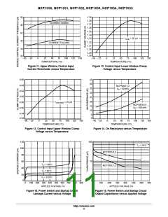
Control Input
The Control Input pin circuit has parallel source follower
input stages with voltage clamps set at 1.35 and 4.6 V.
Current sources clamp the input current through the
http://onsemi.com
14

 ONSEMI [ ONSEMI ]