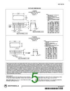
MC10216
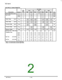
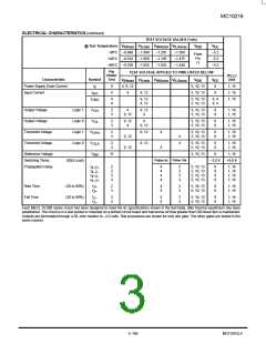
ELECTRICAL CHARACTERISTICS (continued)
TEST VOLTAGE VALUES (Volts)
@ Test Temperature
V
V
ILmin
V
V
V
BB
V
EE
IHmax
IHAmin
ILAmax
–30°C –0.890
+25°C –0.810
+85°C –0.700
–1.890
–1.850
–1.825
–1.205
–1.105
–1.035
–1.500
–1.475
–1.440
–5.2
–5.2
–5.2
From
Pin
11
Pin
Under
Test
TEST VOLTAGE APPLIED TO PINS LISTED BELOW
(V
CC
)
Characteristic
Power Supply Drain Current
Input Current
Symbol
Gnd
V
V
ILmin
V
V
V
BB
V
EE
IHmax
IHAmin
ILAmax
I
E
8
4
4, 9, 12
4
5, 10, 13
5, 10, 13
8
1, 16
1, 16
1, 16
I
9, 12
8
inH
I
4
9
9, 12
4, 12
5, 10, 13
5, 10, 13
8, 4
8, 9
CBO
Output Voltage
Logic 1
Logic 0
Logic 1
Logic 0
V
2
3
4
9, 12
9, 12
4
5, 10, 13
5, 10, 13
8
8
1, 16
1, 16
OH
Output Voltage
V
2
3
9, 12
4
4
9, 12
5, 10, 13
5, 10, 13
8
8
1, 16
1, 16
OL
Threshold Voltage
Threshold Voltage
Reference Voltage
V
OHA
2
3
9, 12
9, 12
4
4
5, 10, 13
5, 10, 13
8
8
1, 16
1, 16
9, 12
9, 12
4
4
V
OLA
2
3
5, 10, 13
5, 10, 13
8
8
1, 16
1, 16
V
11
5, 10, 13
8
1, 16
BB
Pulse Out
Switching Times
(50Ω Load)
Pulse In
–3.2 V
+2.0 V
Propagation Delay
t
t
t
t
2
2
3
3
4
4
4
4
2
2
3
3
5, 10, 13
5, 10, 13
5, 10, 13
5, 10, 13
8
8
8
8
1, 16
1, 16
1, 16
1, 16
4+2+
4–2–
4+3–
4–3+
Rise Time
Fall Time
(20 to 80%)
(20 to 80%)
t
t
2
3
4
4
2
3
5, 10, 13
5, 10, 13
8
8
1, 16
1, 16
2+
3+
t
t
2
3
4
4
2
3
5, 10, 13
5, 10, 13
8
8
1, 16
1, 16
2–
3–
Each MECL 10,000 series circuit has been designed to meet the dc specifications shown in the test table, after thermal equilibrium has been
established. The circuit is in a test socket or mounted on a printed circuit board and transverse air flow greater than 500 linear fpm is maintained.
Outputs are terminated through a 50–ohm resistor to –2.0 volts. Test procedures are shown for only one gate. The other gates are tested in the
same manner.
MECL Data
3–199
MOTOROLA
DL122 — Rev 6

 ONSEMI [ ONSEMI ]