LA42052
External Components
C1, C2 : Input coupling capacitors, which are recommended to be 1.0μF or less.
The input pin voltage 2V ( about 1.4V).
BE
Determine the polarity orientation of these capacitors based on the DC current from the circuit
connected to the LA42052 front end.
C3
C4
C5
: The recommended value for the Ripple filter capacitor is 100μF.
: The recommended value for the P.P capacitor 4.7μF. It is a capacitor for there being small Pop sound.
: Power supply capacitor.
C6, C7 : The recommended value for the output capacitor is 470μF.
1. Standby Function (Pin 5)
By means of controlling pin 5 to high and low, the power
Supply can be set to ON and OFF.
Control Voltage of pin 5
Pin 5 voltage
Amplifier
Standby
ON
0 to 0.5
OFF
1.0 to 5.0
ON
OFF
When the impression voltage of V is high,
S
I want to stop 5 pin inflow current.
R
STB
2kΩ
V
S
5
Restriction resistance (R ) is inserted in a case.
STB
2kΩ
VS = 5V, R
STB
= 5.1kΩ
5 pin inflow current = about 750µA
5 pin voltage = about 1.2V
2. Ripple filter and Mute function (Pin 1)
Pin voltage is approx. 1/2 V
CC
The recommended value for the Ripple filter capacitor is 100µF.
Muting :
The output signal can be controlled by connecting pin 1(Ripple filter) to ground via a resistance of 300 to 500Ω.
If resistance is higher than 750Ω, the suppression ratio will decrease.
3. Input Pin (Pin 2,4)
Voltage at the input pins is approx. 2V (about 1.4V)
BE
Determine the polarity orientation of these capacitors based on the DC current from the circuit
Connected to the LA42052 front end.
Input resistance is approx. 30kΩ (typ)
The recommended value for the input capacitor is 1.0µF.
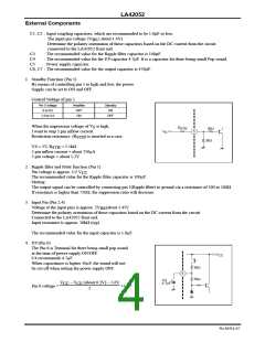
4. P.P (Pin 6)
The Pin 6 is Terminal for there being small pop sound
at the time of power supply ON/OFF.
C4 recommends 4.7µF.
V
CC
When capacitance is higher 10µF, the sound will not
be cut off when setting the power supply OFF.
5kΩ
5kΩ
6
C4
4.7μF
+
V
– V
(about 0.3V) – 5.6V
2
CC
CE
Pin 6 voltage =
+5.6V
No.A0314-4/7

 ONSEMI [ ONSEMI ]