BZX85C3V3RL Series
APPLICATION NOTE
TJ = TL + ∆TJL
.
Since the actual voltage available from a given zener
∆TJL = θJLPD.
diode is temperature dependent, it is necessary to determine
junction temperature under any set of operating conditions
in order to calculate its value. The following procedure is
recommended:
θ
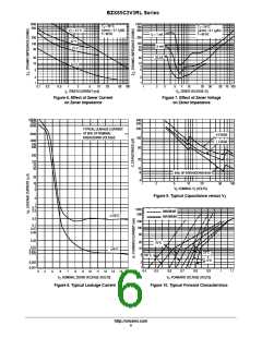
may be determined from Figure 3 for dc power
conditions. For worst-case design, using expected limits of
I , limits of P and the extremes of T (∆T ) may be
JL
Z
D
J
J
Lead Temperature, T , should be determined from:
L
estimated. Changes in voltage, V , can then be found from:
Z
TL = θLAPD + TA.
∆V = θVZ ∆TJ.
θ
is the lead-to-ambient thermal resistance (°C/W) and P
D
LA
θ
, the zener voltage temperature coefficient, is found
VZ
is the power dissipation. The value for θ will vary and
depends on the device mounting method. θ is generally 30
to 40°C/W for the various clips and tie points in common use
and for printed circuit board wiring.
The temperature of the lead can also be measured using a
thermocouple placed on the lead as close as possible to the
tie point. The thermal mass connected to the tie point is
normally large enough so that it will not significantly
respond to heat surges generated in the diode as a result of
pulsed operation once steady-state conditions are achieved.
LA
from Figure 2.
LA
Under high power-pulse operation, the zener voltage will
vary with time and may also be affected significantly by the
zener resistance. For best regulation, keep current
excursions as low as possible.
Surge limitations are given in Figure 5. They are lower
than would be expected by considering only junction
temperature, as current crowding effects cause temperatures
to be extremely high in small spots, resulting in device
degradation should the limits of Figure 5 be exceeded.
Using the measured value of T , the junction temperature
L
may be determined by:
∆T is the increase in junction temperature above the lead
JL
temperature and may be found as follows:
http://onsemi.com
7

 ONSEMI [ ONSEMI ]