EE-SX67/47
EE-SX67/47
Precautions
Do not use the EE-SX at voltage exceeding the rated voltage range,
otherwise the EE-SX may be damaged.
If the load is a relay or other small inductive load, connect the load to
the EE-SX as shown below. Be sure to connect a diode for counter-
voltage absorption.
+
Load
Out
Sensor
OUT
Relay
–
Do not wire power lines or high-tension lines alongside the lines of
Do not make mistakes in wiring, such as mistakes in polarity, other
wise the EE-SX may be damaged.
-
the EE-SX in the same conduit, otherwise the EE-SX may be dam
-
aged or malfunction due to induction. Be sure to wire the lines of the
EE-SX separately from power lines or high-tension lines or lay them
in an exclusive, shielded conduit.
+
Load
Voltage Output
Out
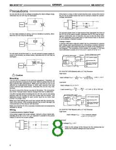
A Sensor with open collector output can be connected to a device
with voltage-input specifications by connecting a resistor between
Sensor
the power supply and output terminals as shown in the following cir
cuit diagram. The resistance of the resistor is normally 4.7 k and
must withstand a power of 0.5 W at 24 V and 0.25 W at 12 V
-
–
Ω
.
Do not short-circuit the load (i.e., do not connect a power supply di
-
Counter (voltage-input model)
+24 V (power supply)
Resistor
rectly to the Sensor) as shown below, otherwise the EE-SX may be
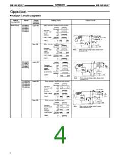
EE-SX67/47 NPN models
damaged.
Output
Input terminal (CP)
Sensor
main
circuit
Load
short-circuiting
Load
+
Input impedance:
approx. 4.7 kΩ
Out
Sensor
–
EE-SX47/67 NPN Models with a 4.7-kΩ Resistor
High level:
!
Caution
Z
R+Z
4.7 k
4.7 k + 4.7 k
V
CC
=
x 24 V = 12 V
Input voltage (V ) =
H
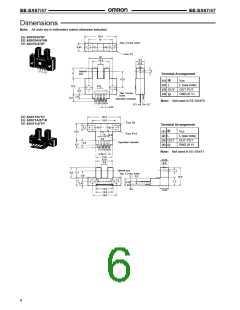
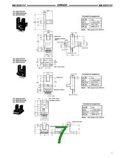
Mounting
The EE-SX is a Sensor to be built into equipment. Therefore, no
special protective measures have been taken to protect the EE-SX
from external light disturbance. Make sure that the EE-SX is not
affected by incandescent lamps or other light sources that may
cause external light disturbance, otherwise the EE-SX may mal-
function.
Low level:
Input voltage (V
)
x
0.4 V
L
V
CC
24 V
R
=
=
5.1 mA
x
50 to 100 mA
Load current (I ) =
C
Be sure to mount the Sensor securely to flat plates. The characteris
-
R
tics of the Through-beam Sensor change if the slot is deformed.
Use M3.0 screws when mounting the EE-SX. Be sure to use spring
washers with the screws so that the screws will not loosen. The
tightening torque applied to each screw must be no more than
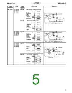
EE-SX67/47 PNP models
Sensor
+24 V (power supply)
Input terminal (CP)
Resistor
0.59 N
S m (6 kgf S cm).
main
Output
circuit
Make sure that nothing will come into contact with the sensing ele
-
ment of the Sensor. If the sensing element has scratch damage, the
characteristics of the Sensor will decrease.
Input impedance:
approx. 4.7 kΩ
Make sure that the EE-SX is securely mounted and not loosened by
vibration or shock.
EE-SX47/67 PNP Models with a 4.7-kΩ Resistor
Wiring
High level:
Countermeasures Against Surge
If the power supply has surge voltage, connect a Zener diode with
-
Input voltage (V
)
= Vcc–residual voltage
24 V–1.3 V=22.7 V
H
standing 30 to 35 V or 0.1 to 1- F capacitor in parallel to the power
µ
[
supply to absorb the surge voltage.
Low level:
Input voltage (V
)
[0 V
L
0.1 to 1 µF
Note: Refer to the ratings of the Sensor for the relationship be-
tween the residual voltage and load current.
8

 OMRON [ OMRON ELECTRONICS LLC ]