E2R-A01
E2R-A01
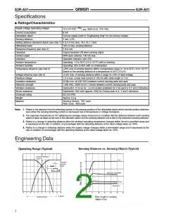
Specifications
■ Ratings/Characteristics
+15%
Supply voltage (operating voltage)
12 to 24 VDC
8 mA
/
, ripple (p-p): 10% max.
-10%
Current consumption
Detectable object
Sensing distance
Ferrous metals (refer to “Engineering Data” for non-ferrous metals)
5 mm ±15%
Setting distance (standard object) (see note 1) 0 to 3.4 mm (iron, 18 x 18 x 1 mm)
Differential travel
10% of max. sensing distance
Response frequency (see note 2)
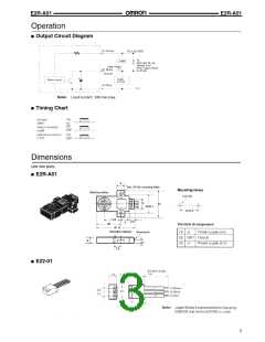
Operation
5 kHz min.
Output transistor ON when sensing object
NPN open collector, 100 mA max.
Operation indicator (red LED)
Control output
Indicators
Ambient temperature
Ambient humidity
Operating: -10 to 55°C (14 to 131°F) with no freezing
Operating: 35% to 85% with no condensation
Temperature influence (see note 3)
±20% max of sensing distance within a temperature range of -10 to 55°C (14 to 131°F)
based on the sensing distance at a temperature of 23°C (73.4°F)
Voltage influence (see note 4)
Residual voltage
Insulation resistance
Dielectric strength
Vibration resistance
Shock resistance
Enclosure rating
Weight
±2.5% max. of sensing distance within a range of ±10% of rated voltage
1.0 V max. (under load current of 100 mA with cable length of 1 m)
50 MΩ min. (at 500 VDC) between current carrying parts and case
1,000 VAC, 50/60 Hz for 1 minute between current carrying parts and case
Destruction: 10 to 55 Hz, 1.5 mm double amplitude for 2 hrs each in X,Y and Z directions
Destruction: 500 m/s2 (approx. 50G) for 3 times each in X, Y and Z directions
IEC144 IP50
Approx. 5.5 g
Material
Sensing Surface: PBT resin
Rear cover: ABS resin
Note: 1. Refers to the distance from the detecting surface to the passing position of the detectable object which permits positive detection
even when the sensing detecting surface is decreased due to temperature or voltage fluctuation.
2. The response frequencies for DC switching are average values measured on condition that the distance between each sensing
object is twice as large as the size of the standard object and the sensing distance set is half of the maximum sensing distance.
3. Refers to a change in detecting distance when the ambient operating temperature changes within Omron’s specified range and
is expressed as the rate of variation (in percentage) with the detecting distance at the rated voltage taken as 100%.
4. Refers to a change in detecting distance when the supply voltage changes within a permissible range and is expressed as the
rate of variation (in percentage) with the detecting distance at the rated voltage taken as 100%.
Engineering Data
2

 OMRON [ OMRON ELECTRONICS LLC ]