E2E
I/O Circuit Diagrams
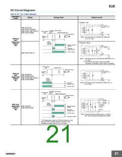
E2E-X@D@ DC 2-Wire Models
Operation
mode
Model
Timing Chart
Output circuit
Polarity: Yes
1
Load
+V
Brown
E2E-X@D1-N
Prox-
imity
Sensor
main
E2E-X@D1-M1G(J)
E2E-X@D1-(M1TGJ)-U
E2E-X@D1-M3G
Set position
Unstable
sensing
area
Non-sensing
area
circuit
Stable sensing area
Proximity Sensor
4
0 V
Blue
Sensing
object
Note: The load can be connected to either the
+V or 0 V side.
Without
self-
diagnostic
output:
NO
100 80
0
(%)
Rated
sensing
distance
Polarity: None
ON
Setting indicator
(green)
4
OFF
ON
Load
+V
(0 V)
Operation
indicator (red)
Prox-
imity
Sensor
main
circuit
OFF
ON
Control output
OFF
E2E-X@D1-M1J-T
3
0 V
(+V)
Note 1. The load can be connected to either the +V or
0 V side.
2. The E2E-X@D1-M1J-T has no polarity.
Therefore, terminals 3 and 4 have no polarity.
Non-sensing
area
Sensing area
Proximity Sensor
1
Load
Brown
Sensing
object
+V
Prox-
imity
Sensor
main
circuit
2
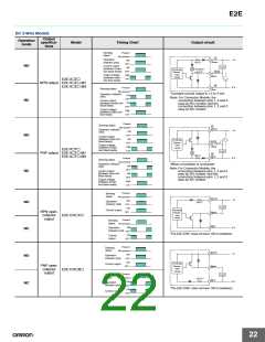
Without
E2E-X@D2-N
self-
100
0
(%)
E2E-X@D2-M1G
diagnostic
E2E-X@D2-(M1TGJ)-U
output:
Rated
E2E-X@D2-M3G
NC
sensing
distance
0 V
Blue
ON
OFF
Note: The load can be connected to either the +V
or 0 V side.
Operation
indicator (red)
ON
Control output
OFF
Unstable
Non-sensing sensing
Set position
area
area
Stable sensing area
Proximity Sensor
Sensing
object
Brown (4)
Load
+V
100 80
0
(%)
Load
Rated
sensing
distance
Prox-
+V
Orange (2)
imity
ON
With self-
diagnostic E2E-X@D1S
Sensor
main
circuit
(diagnostic
output)
OFF Setting indicator
(green)
ON
output:
NO
E2E-X@D1S-M1
Blue (3)
OFF Operation
indicator (red)
ON
0
OFF
ON
Control output
Note: Connect both the loads to the +V side of
the control output and diagnostic output.
Diagnostic output*
OFF
* The diagnostic output is ON when there is a coil
burnout or the sensing object is located in the
unstable sensing area for 0.3 s or longer.
21

 OMRON [ OMRON ELECTRONICS LLC ]