FEDL2250DIGEST-01
OKI Semiconductor
ML2252/54-XXX, ML22Q54
Converting PWM Signal to Analog Signal
Examples of circuits that convert the PWM output signal to an Analog signal when PWM output is selected
(OPTANA pin = “H”) are given below.
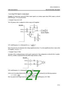
1. Example Using Active LPF
The LPF primary side is configured as below using an OP amplifier.
C1
ML2250f
R2
R1
R1
OUT(+)
OUT(–)
–
+
Speaker amplifier
R2
C1
R3
R3
C2
1
LPC cutoff frequency, f , is determined by
fC =
C
2πR2C1
Ratio of resistors R1 to R2 determines the voltage amplification factor. To set the amplification factor 2 times of the
OP amplifier, set R1:R2 = 1:2.
2. Example Using LC Filter
Secondary LPF is configured using a coil (L) and a capacitor (C). This configuration can directly drive a speaker.
However, a buffer is required between the PWM output and the LC filter.
ML2250f
L
OUT(+)
C
L
OUT(–)
C
1
LPF cutoff frequency, fC, is determined by
.
fC =
LC
2π√
In the case of secondary Butterworth type LC filter, the constants are obtained by the following equations:
1
2πfC
1
L = 1.4142 ×
C =
1.412 × RL × (2πfC)
Here, RL stands for the output load resistance and fC stands for cutoff frequency of LC filter.
27/31

 OKI [ OKI ELECTRONIC COMPONETS ]