Philips Semiconductors
Product specication
I2C-bus controlled 4 45 Watt power
amplier and multiple voltage regulator
TDA8589J; TDA8589xJ
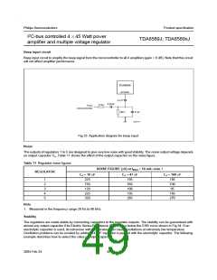
Beep input circuit
Beep input circuit to amplify the beep signal from the microcontroller to all 4 amplifiers (gain = 0 dB). Note that this circuit
will not affect amplifier performance.
TDA8589
ACGND
2.2
F
0.22
F
1.7 k
From
microcontroller
100
47 pF
Fig.33 Application diagram for beep input.
Noise
The outputs of regulators 1 to 5 are designed to give very low noise with good stability. The noise output voltage depends
on output capacitor Co. Table 11 shows the affect of the output capacitor on the noise figure.
Table 11 Regulator noise gures
NOISE FIGURE ( V) at IREG = 10 mA; note 1
REGULATOR
Co = 10
F
Co = 47
F
Co = 100 F
1
2
3
4
5
225
750
120
225
320
195
550
100
195
285
185
530
95
185
270
Note
1. Measured in the frequency range 20 Hz to 80 kHz.
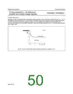
Stability
The regulators are made stable by connecting capacitors to the regulator outputs. The stability can be guaranteed with
almost any output capacitor if its Electric Series Resistance (ESR) stays below the ESR curve shown in Fig.34. If an
electrolytic capacitor is used, its behaviour with temperature can cause oscillations at extremely low temperature.
Oscillation problems can be avoided by adding a 47 nF capacitor in parallel with the electrolytic capacitor. The following
example describes how to select the value of output capacitor.
2004 Feb 24
49

 NXP [ NXP ]