Philips Semiconductors
Product specification
Double-balanced mixer and oscillator
NE/SA612A
Besides excellent low power performance well into VHF, the
NE/SA612A is designed to be flexible. The input, output, and
oscillator ports can support a variety of configurations provided the
designer understands certain constraints, which will be explained
here.
permissible oscillation frequency. If the required L.O. is beyond
oscillation limits, or the system calls for an external L.O., the
external signal can be injected at Pin 6 through a DC blocking
capacitor. External L.O. should be 200mV
maximum.
minimum to 300mV
P-P
P-P
The RF inputs (Pins 1 and 2) are biased internally. They are
symmetrical. The equivalent AC input impedance is approximately
1.5k || 3pF through 50MHz. Pins 1 and 2 can be used
interchangeably, but they should not be DC biased externally. Figure
5 shows three typical input configurations.
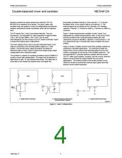
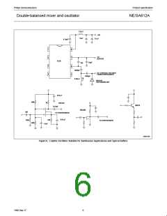
Figure 7 shows several proven oscillator circuits. Figure 7a is
appropriate for cordless phones/cellular radio. In this circuit a third
overtone parallel-mode crystal with approximately 5pF load
capacitance should be specified. Capacitor C3 and inductor L1 act
as a fundamental trap. In fundamental mode oscillation the trap is
omitted.
The mixer outputs (Pins 4 and 5) are also internally biased. Each
output is connected to the internal positive supply by a 1.5kΩ
resistor. This permits direct output termination yet allows for
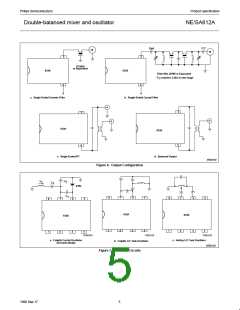
balanced output as well. Figure 6 shows three single-ended output
configurations and a balanced output.
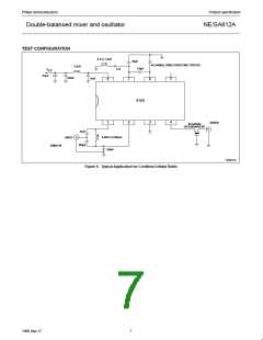
Figure 8 shows a Colpitts varacter tuned tank oscillator suitable for
synthesizer-controlled applications. It is important to buffer the
output of this circuit to assure that switching spikes from the first
counter or prescaler do not end up in the oscillator spectrum. The
dual-gate MOSFET provides optimum isolation with low current.
The FET offers good isolation, simplicity, and low current, while the
bipolar circuits provide the simple solution for non-critical
applications. The resistive divider in the emitter-follower circuit
should be chosen to provide the minimum input signal which will
assume correct system operation.
The oscillator is capable of sustaining oscillation beyond 200MHz in
crystal or tuned tank configurations. The upper limit of operation is
determined by tank “Q” and required drive levels. The higher the Q
of the tank or the smaller the required drive, the higher the
612A
612A
612A
1
2
1
2
1
2
INPUT
a. Single-Ended Tuned Input
b. Balanced Input (For Attenuation
of Second-Order Products)
c. Single-Ended Untuned Input
SR00103
Figure 5. Input Configuration
4
1990 Sep 17

 NXP [ NXP ]