M28R400CT, M28R400CB
ure 19., Erase Suspend & Resume Flowchart and
Pseudo Code, for flowcharts for using the Pro-
gram/Erase Resume command.
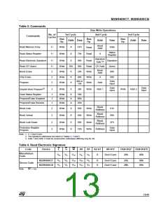
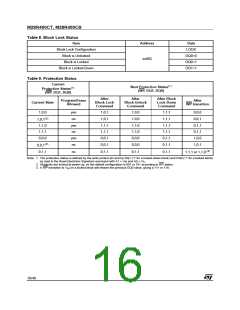
The lock status can be monitored for each block
using the Read Electronic Signature command.
Table 9. shows the protection status after issuing
a Block Lock command.
Protection Register Program Command
The Block Lock bits are volatile, once set they re-
main set until a hardware reset or power-down/
power-up. They are cleared by a Blocks Unlock
command. Refer to the section, BLOCK LOCK-
ING, for a detailed explanation.
The Protection Register Program command is
used to Program the 64 bit user One-Time-Pro-
grammable (OTP) segment of the Protection Reg-
ister. The segment is programmed 16 bits at a
time. When shipped all bits in the segment are set
to ‘1’. The user can only program the bits to ‘0’.
Block Unlock Command
Two write cycles are required to issue the Protec-
tion Register Program command.
The Blocks Unlock command is used to unlock a
block, allowing the block to be programmed or
erased. Two Bus Write cycles are required to is-
sue the Blocks Unlock command.
■
The first bus cycle sets up the Protection
Register Program command.
■
The first bus cycle sets up the Block Unlock
command.
■
The second latches the Address and the Data
to be written to the Protection Register and
starts the Program/Erase Controller.
■
The second Bus Write cycle latches the block
address.
Read operations output the Status Register con-
tent after the programming has started.
The lock status can be monitored for each block
using the Read Electronic Signature command.
Table 9. shows the protection status after issuing
a Block Unlock command. Refer to the section,
BLOCK LOCKING, for a detailed explanation.
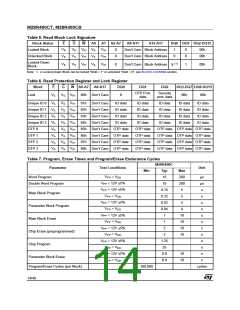
The segment can be protected by programming bit
1 of the Protection Lock Register. Bit 1 of the Pro-
tection Lock Register protects bit 2 of the Protec-
tion Lock Register. Programming bit 2 of the
Protection Lock Register will result in a permanent
protection of the Security Block (see Figure 5., Se-
curity Block Memory Map). Attempting to program
a previously protected Protection Register will re-
sult in a Status Register error. The protection of
the Protection Register and/or the Security Block
is not reversible.
Block Lock-Down Command
A locked block cannot be Programmed or Erased,
or have its protection status changed when WP is
low, VIL. When WP is high, VIH, the Lock-Down
function is disabled and the locked blocks can be
individually unlocked by the Block Unlock com-
mand.
The Protection Register Program cannot be sus-
pended. See APPENDIX C., Figure 21., Protec-
tion Register Program Flowchart and Pseudo
Code, for the flowchart for using the Protection
Register Program command.
Two Bus Write cycles are required to issue the
Block Lock-Down command.
■
The first bus cycle sets up the Block Lock
command.
■
The second Bus Write cycle latches the block
address.
Block Lock Command
The Block Lock command is used to lock a block
and prevent Program or Erase operations from
changing the data in it. All blocks are locked at
power-up or reset.
Two Bus Write cycles are required to issue the
Block Lock command.
The lock status can be monitored for each block
using the Read Electronic Signature command.
Locked-Down blocks revert to the locked (and not
locked-down) state when the device is reset on
power-down. Table 9. shows the protection status
after issuing a Block Lock-Down command. Refer
to the section, BLOCK LOCKING, for a detailed
explanation.
■
The first bus cycle sets up the Block Lock
command.
■
The second Bus Write cycle latches the block
address.
12/48

 NUMONYX [ NUMONYX B.V ]