M25PX64
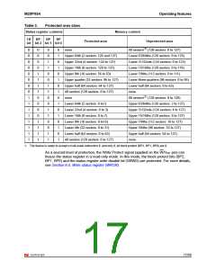
Table 3.
Operating features
Protected area sizes
Status register contents
Memory content
TB
BP
BP
BP
Protected area
Unprotected area
bit bit 2 bit 1 bit 0
0
0
0
0
0
0
0
0
1
1
1
1
1
1
1
1
0
0
0
0
1
1
1
1
0
0
0
0
1
1
1
1
0
0
1
1
0
0
1
1
0
0
1
1
0
0
1
1
0
1
0
1
0
1
0
1
0
1
0
1
0
1
0
1
none
All sectors(1) (128 sectors: 0 to 127)
Lower 63/64ths (126 sectors: 0 to 125)
Lower 31/32nds (124 sectors: 0 to 123)
Lower 15/16ths (120 sectors: 0 to 119)
Lower 7/8ths (112 sectors: 0 to 111)
Lower three-quarters (96 sectors: 0 to 95)
Lower half (64 sectors: 0 to 63)
none
Upper 64th (2 sectors: 126 and 127)
Upper 32nd (4 sectors: 124 to 127)
Upper 16th (8 sectors: 120 to 127)
Upper 8th (16 sectors: 56 to 63)
Upper quarter (32 sectors: 96 to 127)
Upper half (64 sectors: 64 to 127)
All sectors (128 sectors: 0 to 127)
none
All sectors(1) (128 sectors: 0 to 128)
Upper 63/64ths (126 sectors: 2 to 127)
Upper 31/32nds (124 sectors: 4 to 127)
Upper 15/16ths (120 sectors: 8 to 127)
Upper 7/8ths (112 sectors: 16 to 127)
Upper 3/4ths (96 sectors: 32 to 127)
Upper half (64 sectors: 64 to 127)
none
Lower 64th (2 sectors: 0 to1)
Lower 32nd (4 sectors: 0 to 3)
Lower 16th (8 sectors: 0 to 7)
Lower 8th (16 sectors: 0 to15)
Lower 4th (32 sectors: 0 to 31)
Lower half (64 sectors: 0 to 63)
All sectors (128 sectors: 0 to 127)
1. The device is ready to accept a bulk erase instruction if, and only if, all block protect (BP2, BP1, BP0) are 0.
As a second level of protection, the Write Protect signal (applied on the W/VPP pin) can
freeze the status register in a read-only mode. In this mode, the block protect bits (BP2,
BP1, BP0) and the status register write disable bit (SRWD) are protected. For more details,
see Section 6.5: Write status register (WRSR).
17/68

 NUMONYX [ NUMONYX B.V ]