DC and AC parameters
M25P32
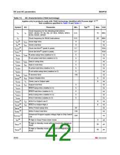
Table 14.
Symbol
AC characteristics (T9HX technology)
Applies only to products made with T9HX technology, identified with Process digit “4”(1)
Test conditions specified in Table 10 and Table 11
Alt.
Parameter
Min.
Typ.(2)
Max. Unit
Clock frequency for the following instructions:
fC
fC FAST_READ, PP, SE, BE, DP, RES, WREN, WRDI,
RDID, RDSR, WRSR
D.C.
75
33
MHz
fR
Clock frequency for READ instructions
tCLH Clock High time
D.C.
9
MHz
ns
(3)
tCH
(2)
tCL
tCLL Clock Low time
9
ns
(4)
tCLCH
Clock rise time(5) (peak to peak)
Clock fall time(5) (peak to peak)
tCSS S active setup time (relative to C)
S not active hold time (relative to C)
tDSU Data In setup time
0.1
0.1
5
V/ns
V/ns
ns
(4)
tCHCL
tSLCH
tCHSL
tDVCH
tCHDX
tCHSH
tSHCH
tSHSL
5
ns
2
ns
tDH Data In hold time
5
ns
S active hold time (relative to C)
S not active setup time (relative to C)
tCSH S deselect time
5
ns
5
ns
100
ns
(4)
tSHQZ
tDIS Output Disable time
8
8
ns
tCLQV
tCLQX
tHLCH
tCHHH
tHHCH
tCHHL
tV Clock Low to Output valid
tHO Output hold time
ns
0
5
5
5
5
ns
HOLD setup time (relative to C)
HOLD hold time (relative to C)
HOLD setup time (relative to C)
HOLD hold time (relative to C)
tLZ HOLD to Output Low-Z
tHZ HOLD to Output High-Z
Write Protect setup time
ns
ns
ns
ns
(4)
tHHQX
8
8
ns
(4)
tHLQZ
ns
(6)
tWHSL
20
ns
(6)
tSHWL
Write Protect hold time
100
ns
Enhanced Program supply voltage High to Chip Select
Low
(7)
tVPPHSL
200
ns
µs
µs
(4)
tDP
S High to Deep Power-down mode
3
S High to Standby mode without Electronic Signature
Read
(4)
tRES1
30
S High to Standby mode with Electronic Signature
Read
(4)
tRES2
30
µs
42/53

 NUMONYX [ NUMONYX B.V ]