M25P32
Operating features
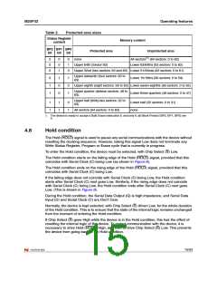
Table 2.
Protected area sizes
Status Register
content
Memory content
BP2 BP1 BP0
Protected area
Unprotected area
bit
bit
bit
0
0
0
0
0
1
0
1
0
none
Upper 64th (Sector 63)
All sectors(1) (64 sectors: 0 to 63)
Lower 63/64ths (63 sectors: 0 to 62)
Upper 32nd (two sectors: 62 and 63) Lower 31/32nds (62 sectors: 0 to 61)
Upper sixteenth (four sectors: 60 to
Lower 15/16ths (60 sectors: 0 to 59)
63)
0
1
1
1
0
0
1
0
1
Upper eighth (eight sectors: 56 to 63) Lower seven-eighths (56 sectors: 0 to 55)
Upper quarter (sixteen sectors: 48 to
Lower three-quarters (48 sectors: 0 to 47)
63)
Upper half (thirty-two sectors: 32 to
Lower half (32 sectors: 0 to 31)
63)
1
1
1
1
0
1
All sectors (64 sectors: 0 to 63)
none
1. The device is ready to accept a Bulk Erase instruction if, and only if, all Block Protect (BP2, BP1, BP0) are
0.
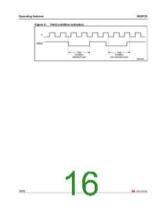
4.8
Hold condition
The Hold (HOLD) signal is used to pause any serial communications with the device without
resetting the clocking sequence. However, taking this signal Low does not terminate any
Write Status Register, Program or Erase cycle that is currently in progress.
To enter the Hold condition, the device must be selected, with Chip Select (S) Low.
The Hold condition starts on the falling edge of the Hold (HOLD) signal, provided that this
coincides with Serial Clock (C) being Low (as shown in Figure 6).
The Hold condition ends on the rising edge of the Hold (HOLD) signal, provided that this
coincides with Serial Clock (C) being Low.
If the falling edge does not coincide with Serial Clock (C) being Low, the Hold condition
starts after Serial Clock (C) next goes Low. Similarly, if the rising edge does not coincide
with Serial Clock (C) being Low, the Hold condition ends after Serial Clock (C) next goes
Low. (This is shown in Figure 6).
During the Hold condition, the Serial Data Output (Q) is high impedance, and Serial Data
Input (D) and Serial Clock (C) are Don’t Care.
Normally, the device is kept selected, with Chip Select (S) driven Low, for the whole duration
of the Hold condition. This is to ensure that the state of the internal logic remains unchanged
from the moment of entering the Hold condition.
If Chip Select (S) goes High while the device is in the Hold condition, this has the effect of
resetting the internal logic of the device. To restart communication with the device, it is
necessary to drive Hold (HOLD) High, and then to drive Chip Select (S) Low. This prevents
the device from going back to the Hold condition.
15/53

 NUMONYX [ NUMONYX B.V ]