M25P32
Instructions
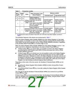
Table 7.
Protection modes
Memory content
Protected area(1) Unprotected area(1)
W/VPP SRWD
Write Protection of the
Status Register
Mode
signal
bit
1
0
0
0
Status Register is
Writable (if the WREN
instruction has set the
WEL bit)
Protected against
Page Program,
Sector Erase and
Bulk Erase
Ready to accept
Page Program and
Sector Erase
Software
Protected
(SPM)
The values in the SRWD,
BP2, BP1 and BP0 bits
can be changed
instructions
1
0
1
1
Status Register is
Hardware write protected
Protected against
Page Program,
Sector Erase and
Bulk Erase
Ready to accept
Page Program and
Sector Erase
Hardware
Protected
(HPM)
The values in the SRWD,
BP2, BP1 and BP0 bits
cannot be changed
instructions
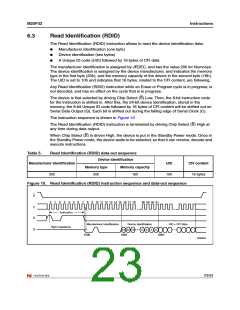
1. As defined by the values in the Block Protect (BP2, BP1, BP0) bits of the Status Register, as shown in
Table 2.
The protection features of the device are summarized in Table 7.
When the Status Register Write Disable (SRWD) bit of the Status Register is 0 (its initial
delivery state), it is possible to write to the Status Register provided that the Write Enable
Latch (WEL) bit has previously been set by a Write Enable (WREN) instruction, regardless
of the whether Write Protect (W/V ) is driven High or Low.
PP
When the Status Register Write Disable (SRWD) bit of the Status Register is set to 1, two
cases need to be considered, depending on the state of Write Protect (W/V ):
PP
●
If Write Protect (W/V ) is driven High, it is possible to write to the Status Register
PP
provided that the Write Enable Latch (WEL) bit has previously been set by a Write
Enable (WREN) instruction.
●
If Write Protect (W/V ) is driven Low, it is not possible to write to the Status Register
PP
even if the Write Enable Latch (WEL) bit has previously been set by a Write Enable
(WREN) instruction. (Attempts to write to the Status Register are rejected, and are not
accepted for execution). As a consequence, all the data bytes in the memory area that
are software protected (SPM) by the Block Protect (BP2, BP1, BP0) bits of the Status
Register, are also hardware protected against data modification.
Regardless of the order of the two events, the Hardware Protected Mode (HPM) can be
entered:
●
by setting the Status Register Write Disable (SRWD) bit after driving Write Protect
(W/V ) Low
PP
●
or by driving Write Protect (W/V ) Low after setting the Status Register Write Disable
PP
(SRWD) bit.
The only way to exit the Hardware Protected Mode (HPM) once entered is to pull Write
Protect (W/V ) High.
PP
If Write Protect (W/V ) is permanently tied High, the Hardware Protected Mode (HPM) can
PP
never be activated, and only the Software Protected Mode (SPM), using the Block Protect
(BP2, BP1, BP0) bits of the Status Register, can be used.
27/53

 NUMONYX [ NUMONYX B.V ]