Electrical Characteristics: (TC = +25°C unless otherwise specified)
Parameter
Symbol
Test Conditions
Min Typ Max Unit
T = +25°C
–
–
–
–
10
2
µA
mA
mA
mA
V
Peak Forward or Reverse
Blocking Current
I
I
,
Rated V
or V
,
J
DRM
DRM
Gate Open
RRM
RRM
T = +100°C
J
I
–
10
–
30
60
Gate Trigger Current (Continuous DC)
Gate Trigger Voltage (Continuous DC)
V = 7V, R = 100Ω,
GT
D
L
Note 3
T = –40°C
C
–
V
GT
V = 7V, R = 100Ω
D
–
0.75 1.5
L
T = –40°C
–
–
–
2.5
V
C
T = +100°C
J
0.2
–
–
V
Forward “ON” Voltage
v
I
= 15.7A, Note 4
1.4 2.0
V
TM
TM
Holding Current
I
V = 7V, Gate Open
–
10
–
30
60
–
mA
mA
µs
µs
µs
H
D
T = –40°C
–
C
Turn–On Time (t + t )
t
t
I = 20mA, I = 5A, V = Rated V
DRM
–
1
d
r
on
G
F
D
Turn–Off Time
–
15
25
–
I = 5A, I = 5A,
off
F
R
dv/dt = 30V/µs
T = +100°C,
J
–
–
V = Rated V
D
DRM
Forward Voltage Application Rate
(Exponential)
dv/dt Gate Open, T = +100°C,
–
50
–
V/µs
J
V = Rated V
D
DRM
Note 3. For optimum operation, i.e. faster turn–on, lower switching losses, best di/dt capability, rec-
ommended IGT = 200mA minimum.
Note 4. Pulsed, 1ms max., Duty Cycle ≤ 1%.
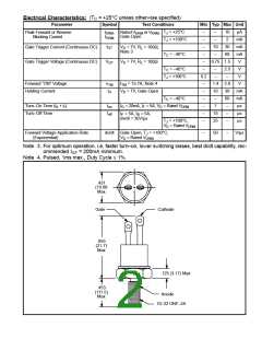
.431
(10.98
Max
Gate
Cathode
.855
(21.7)
Max
.125 (3.17) Max
.453
(111.5)
Max
Anode
10–32 UNF–2A

 NTE [ NTE ELECTRONICS ]