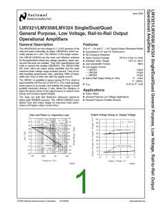
5V AC Electrical Characteristics
Unless otherwise specified, all limits guaranteed for T J = 25˚C, V+ = 5V, V− = 0V, VCM = 2.0V, VO = V+/2 and R L 1MΩ.
Boldface limits apply at the temperature extremes.
>
Typ
(Note 6)
Limit
(Note 7)
Symbol
SR
Parameter
Conditions
Units
Slew Rate
(Note 9)
1
V/µs
MHz
Deg
dB
GBWP
Φm
Gain-Bandwidth Product
Phase Margin
CL = 200pF
1
60
10
39
Gm
Gain Margin
en
Input-Referred Voltage Noise
f = 1kHz
f = 1kHz
in
Input-Referred Current Noise
0.21
Note 1: Absolute Maximum Ratings indicate limits beyond which damage to the device may occur. Operating Ratings indicate conditions for which the device is
intended to be functional, but specific performance is not guaranteed. For guaranteed specifications and the test conditions, see the Electrical Characteristics.
Note 2: Human body model, 1.5kΩ in series with 100pF. Machine model, 0Ω in series with 200pF.
+
Note 3: Shorting output to V will adversely affect reliability.
-
Note 4: Shorting output to V will adversely affect reliability.
Note 5: The maximum power dissipation is a function of T
, θ , and T . The maximum allowable power dissipation at any ambient temperature is P =
A D
J(MAX) JA
(T
–T )/θ . All numbers apply for packages soldered directly into a PC board.
J(MAX)
A JA
Note 6: Typical values represent the most likely parametric norm.
Note 7: All limits are guaranteed by testing or statistical analysis.
-
Note 8: R is connected to V . The output voltage is 0.5V ≤ V ≤ 4.5V.
L
O
Note 9: Connected as voltage follower with 3V step input. Number specified is the slower of the positive and negative slew rates.
Note 10: All numbers are typical, and apply for packages soldered directly onto a PC board in still air.
www.national.com
4

 NSC [ National Semiconductor ]