Electrical Characteristics (Note 2) (Continued)
Note 1: The maximum junction temperature of the LM105 and LM305A is 150˚C, and the LM305 is 85˚C. For operation at elevated temperatures, devices in the
H08C package must be derated based on a thermal resistance of 168˚C/W junction to ambient, or 25˚C/W junction to case. Peak dissipations to 1W are allowable
providing the dissipation rating is not exceeded with the power average over a five second interval for the LM105 and averaged over a two second interval for the
LM305.
Note 2: Unless otherwise specified, these specifications apply for temperatures within the operating temperature range, for input and output voltages within the
range given, and for a divider impedance seen by the feedback terminal of 2 kΩ. Load and line regulation specifications are for a constant junction temperature. Tem-
perature drift effects must be taken into account separately when the unit is operating under conditions of high dissipation.
Note 3: The output currents given, as well as the load regulation, can be increased by the addition of external transistors. The improvement factor will be roughly
equal to the composite current gain of the added transistors.
Note 4: With no external pass transistor.
Note 5: Refer to RETS105X Drawing for military specifications for the LM105.
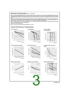
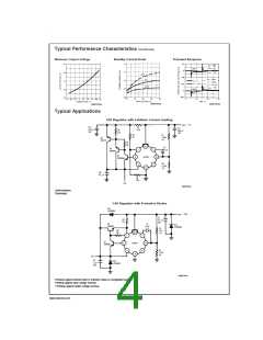
Typical Performance Characteristics
Load Regulation
Load Regulation
Current Limiting
Characteristics
DS007755-16
DS007755-15
DS007755-17
Current Limit Sense Voltage
Short Circuit Current
Optimum Divider Resistance
Values
DS007755-19
DS007755-18
DS007755-20
Minimum Input Voltage
Regulator Dropout Voltage
Supply Voltage Rejection
DS007755-22
DS007755-21
DS007755-23
3
www.national.com

 NSC [ National Semiconductor ]