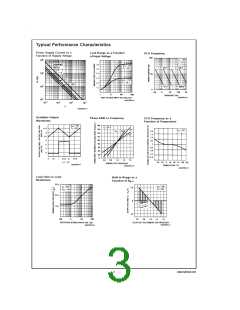
Applications Information
In designing with phase locked loops such as the LM565, the
important parameters of interest are:
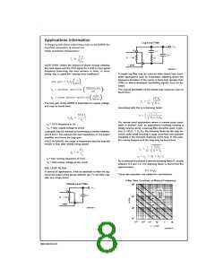
Lag-Lead Filter
FREE RUNNING FREQUENCY
LOOP GAIN: relates the amount of phase change between
the input signal and the VCO signal for a shift in input signal
frequency (assuming the loop remains in lock). In servo
theory, this is called the “velocity error coefficient.”
DS007853-12
A simple lag filter may be used for wide closed loop band-
width applications such as modulation following where the
frequency deviation of the carrier is fairly high (greater than
10%), or where wideband modulating signals must be fol-
lowed.
The natural bandwidth of the closed loop response may be
found from:
The loop gain of the LM565 is dependent on supply voltage,
and may be found from:
Associated with this is a damping factor:
For narrow band applications where a narrow noise band-
width is desired, such as applications involving tracking a
slowly varying carrier, a lead lag filter should be used. In gen-
=
fo VCO frequency in Hz
=
Vc total supply voltage to circuit
<
eral, if 1/R1C1 Ko KD, the damping factor for the loop be-
Loop gain may be reduced by connecting a resistor between
pins 6 and 7; this reduces the load impedance on the output
amplifier and hence the loop gain.
comes quite small resulting in large overshoot and possible
instability in the transient response of the loop. In this case,
the natural frequency of the loop may be found from
HOLD IN RANGE: the range of frequencies that the loop will
remain in lock after initially being locked.
=
fo free running frequency of VCO
R2 is selected to produce a desired damping factor δ, usually
between 0.5 and 1.0. The damping factor is found from the
approximation:
=
Vc total supply voltage to the circuit
THE LOOP FILTER
δ ) π τ2fn
In almost all applications, it will be desirable to filter the sig-
nal at the output of the phase detector (pin 7); this filter may
take one of two forms:
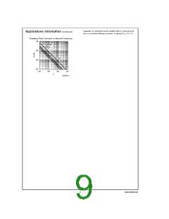
These two equations are plotted for convenience.
Filter Time Constant vs Natural Frequency
Simple Lead Filter
DS007853-11
DS007853-13
www.national.com
8

 NSC [ National Semiconductor ]