unfortunately, in order for this to be true, ground conductors
with zero resistance are necessary. Since real world ground
leads possess finite resistance, currents running through
them will cause finite voltage drops to exist. If two ground re-
turn lines tie into the same path at different points there will
be a voltage drop between them. The first figure below
shows a common ground example where the positive input
ground and the load ground are returned to the supply
ground point via the same wire. The addition of the finite wire
resistance, R2, results in a voltage difference between the
two points as shown below.
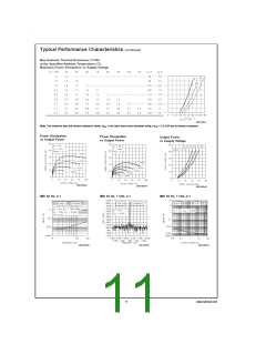
Application Information (Continued)
SUPPLY BYPASSING
The LM3886 has excellent power supply rejection and does
not require a regulated supply. However, to eliminate pos-
sible oscillations all op amps and power op amps should
have their supply leads bypassed with low-inductance ca-
pacitors having short leads and located close to the package
terminals. Inadequate power supply bypassing will manifest
itself by a low frequency oscillation known as “motorboating”
or by high frequency instabilities. These instabilities can be
eliminated through multiple bypassing utilizing a large tanta-
lum or electrolytic capacitor (10 µF or larger) which is used to
absorb low frequency variations and a small ceramic capaci-
tor (0.1 µF) to prevent any high frequency feedback through
the power supply lines.
If adequate bypassing is not provided the current in the sup-
ply leads which is a rectified component of the load current
may be fed back into internal circuitry. This signal causes low
distortion at high frequencies requiring that the supplies be
bypassed at the package terminals with an electrolytic ca-
pacitor of 470 µF or more.
LEAD INDUCTANCE
Power op amps are sensitive to inductance in the output
lead, particularly with heavy capacitive loading. Feedback to
the input should be taken directly from the output terminal,
minimizing common inductance with the load.
Lead inductance can also cause voltage surges on the sup-
plies. With long leads to the power supply, energy is stored in
the lead inductance when the output is shorted. This energy
can be dumped back into the supply bypass capacitors when
the short is removed. The magnitude of this transient is re-
duced by increasing the size of the bypass capacitor near
the IC. With at least a 20 µF local bypass, these voltage
surges are important only if the lead length exceeds a couple
>
feet ( 1 µH lead inductance). Twisting together the supply
and ground leads minimizes the effect.
DS011833-15
The load current IL will be much larger than input bias current
II, thus V1 will follow the output voltage directly, i.e. in phase.
Therefore the voltage appearing at the non-inverting input is
effectively positive feedback and the circuit may oscillate. If
there were only one device to worry about then the values of
R1 and R2 would probably be small enough to be ignored;
however, several devices normally comprise a total system.
Any ground return of a separate device, whose output is in
phase, can feedback in a similar manner and cause instabili-
ties. Out of phase ground loops also are troublesome, caus-
ing unexpected gain and phase errors.
LAYOUT, GROUND LOOPS AND STABILITY
The LM3886 is designed to be stable when operated at a
closed-loop gain of 10 or greater, but as with any other
high-current amplifier, the LM3886 can be made to oscillate
under certain conditions. These usually involve printed cir-
cuit board layout or output/input coupling.
When designing a layout, it is important to return the load
ground, the output compensation ground, and the low level
(feedback and input) grounds to the circuit board common
ground point through separate paths. Otherwise, large cur-
rents flowing along a ground conductor will generate volt-
ages on the conductor which can effectively act as signals at
the input, resulting in high frequency oscillation or excessive
distortion. It is advisable to keep the output compensation
components and the 0.1 µF supply decoupling capacitors as
close as possible to the LM3886 to reduce the effects of PCB
trace resistance and inductance. For the same reason, the
ground return paths should be as short as possible.
The solution to most ground loop problems is to always use
a single-point ground system, although this is sometimes im-
practical. The third figure below is an example of
single-point ground system.
a
The single-point ground concept should be applied rigor-
ously to all components and all circuits when possible. Viola-
tions of single-point grounding are most common among
printed circuit board designs, since the circuit is surrounded
by large ground areas which invite the temptation to run a
device to the closest ground spot. As a final rule, make all
ground returns low resistance and low inductance by using
large wire and wide traces.
In general, with fast, high-current circuitry, all sorts of prob-
lems can arise from improper grounding which again can be
avoided by returning all grounds separately to a common
point. Without isolating the ground signals and returning the
grounds to a common point, ground loops may occur.
Occasionally, current in the output leads (which function as
antennas) can be coupled through the air to the amplifier in-
put, resulting in high-frequency oscillation. This normally
happens when the source impedance is high or the input
leads are long. The problem can be eliminated by placing a
“Ground Loop” is the term used to describe situations occur-
ring in ground systems where a difference in potential exists
between two ground points. Ideally a ground is a ground, but
15
www.national.com

 NSC [ National Semiconductor ]