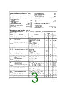
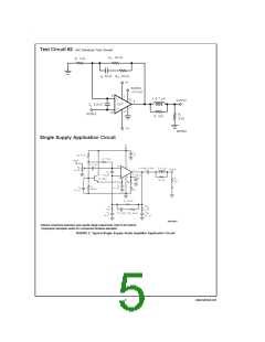
External Components Description
(Figure 1 and Figure 2)
Components
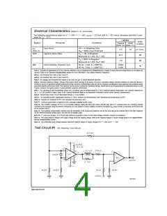
Functional Description
1.
2.
3.
4.
5.
RIN
RA
CA
C
Acts as a volume control by setting the voltage level allowed to the amplifier’s input terminals.
Provides DC voltage biasing for the single supply operation and bias current for the positive input terminal.
Provides bias filtering.
Provides AC coupling at the input and output of the amplifier for single supply operation.
RB
Prevents currents from entering the amplifier’s non-inverting input which may be passed through to the load
upon power-down of the system due to the low input impedance of the circuitry when the under-voltage
circuitry is off. This phenomenon occurs when the supply voltages are below 1.5V.
6.
CC
Reduces the gain (bandwidth of the amplifier) at high frequencies to avoid quasi-saturation oscillations of
(Note 17) the output transistor. The capacitor also suppresses external electromagnetic switching noise created from
fluorescent lamps.
7.
8.
Ri
Inverting input resistance to provide AC Gain in conjunction with Rf1
.
Ci
Feedback capacitor. Ensures unity gain at DC. Also a low frequency pole (highpass roll-off) at:
(Note 17)
=
fc 1/(2πRi Ci)
9.
Rf1
Rf2
Feedback resistance to provide AC Gain in conjunction with Ri.
10.
At higher frequencies feedback resistance works with Cf to provide lower AC Gain in conjunction with Rf1
(Note 17) and Ri. A high frequency pole (lowpass roll-off) exists at:
=
fc [Rf1 Rf2 (s + 1/Rf2Cf)]/[(Rf1 + Rf2)(s + 1/Cf(Rf1 + Rf2))]
11.
12.
Cf
Compensation capacitor that works with Rf1 and Rf2 to reduce the AC Gain at higher frequencies.
(Note 17)
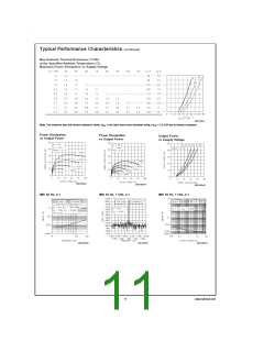
RM
Mute resistance set up to allow 0.5 mA to be drawn from pin 8 to turn the muting function off.
→
RM is calculated using: RM ≤ (|VEE| − 2.6V)/I8 where I8 ≥ 0.5 mA. Refer to the Mute Attenuation vs.
Mute Current curves in the Typical Performance Characteristics section.
13.
14.
CM
Mute capacitance set up to create a large time constant for turn-on and turn-off muting.
Works with CSN to stabilize the output stage by creating a pole that eliminates high frequency oscillations.
RSN
(Note 17)
15.
CSN
Works with RSN to stabilize the output stage by creating a pole that eliminates high frequency oscillations.
(Note 17)
=
fc 1/(2πRSNCSN
)
16.
17.
L
Provides high impedance at high frequencies so that R may decouple a highly capacitive load and reduce
(Note 17) the Q of the series resonant circuit due to capacitive load. Also provides a low impedance at low
frequencies to short out R and pass audio signals to the load.
R
(Note 17)
18.
19.
CS
S1
Provides power supply filtering and bypassing.
Mute switch that mutes the music going into the amplifier when opened.
Note 17: Optional components dependent upon specific design requirements. Refer to the Application Information section for more information.
OPTIONAL EXTERNAL COMPONENT INTERACTION
Although the optional external components have specific desired functions that are designed to reduce the bandwidth and elimi-
nate unwanted high frequency oscillations they may cause certain undesirable effects when they interact. Interaction may occur
for components whose reactances are in close proximity to one another. One example would be the coupling capacitor, CC, and
the compensation capacitor, Cf. These two components act as low impedances to certain frequencies which will couple signals
from the input to the output. Please take careful note of basic amplifier component functionality when designing in these compo-
nents.
The optional external components shown in Figure 2 and described above are applicable in both single and split voltage supply
configurations.
7
www.national.com

 NSC [ National Semiconductor ]