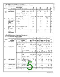
LM340 Electrical Characteristics (Note 4) (Continued)
0˚C ≤ TJ ≤ +125˚C unless otherwise specified
Output Voltage
5V
10V
12V
19V
15V
23V
Symbol
Input Voltage (unless otherwise noted)
Units
Parameter
Conditions
VMIN ≤ VIN ≤ VMAX
Min Typ Max Min Typ Max Min Typ Max
(7.5 ≤ VIN ≤ 20)
(14.8 ≤ VIN
≤
(17.9 ≤ VIN ≤ 30)
V
27)
IO ≤ 500 mA, 0˚C ≤ TJ ≤ +125˚C
VMIN ≤ VIN ≤ VMAX
1.0
1.0
1.0
mA
V
(7 ≤ VIN ≤ 25)
(14.5 ≤ VIN
≤
(17.5 ≤ VIN ≤ 30)
30)
VN
Output Noise
Voltage
TA = 25˚C, 10 Hz ≤ f ≤ 100 kHz
40
75
90
µV
dB
dB
V
Ripple Rejection
IO ≤ 1A, TJ =
25˚C
62
62
80
55
55
72
54
54
70
f = 120 Hz
or IO ≤ 500 mA,
0˚C ≤ TJ ≤ +125˚C
VMIN ≤ VIN ≤ VMAX
(8 ≤ VIN ≤ 18)
(15 ≤ VIN ≤ 25)
(18.5 ≤ VIN
28.5)
2.0
≤
RO
Dropout Voltage
TJ = 25˚C, IO = 1A
f = 1 kHz
2.0
8
2.0
18
V
mΩ
A
Output Resistance
19
Short-Circuit Current TJ = 25˚C
2.1
2.4
1.5
2.4
1.2
Peak Output
Current
TJ = 25˚C
2.4
A
Average TC of VOUT 0˚C ≤ TJ ≤ +125˚C, IO = 5 mA
−0.6
7.5
−1.5
14.6
−1.8
mV/˚C
V
VIN
Input Voltage
Required to
Maintain
TJ = 25˚C, IO ≤ 1A
17.7
Line Regulation
Note 1: Absolute Maximum Ratings are limits beyond which damage to the device may occur. Operating Conditions are conditions under which the device functions
but the specifications might not be guaranteed. For guaranteed specifications and test conditions see the Electrical Characteristics.
Note 2: The maximum allowable power dissipation at any ambient temperature is a function of the maximum junction temperature for operation (T
= 125˚C or
JMAX
150˚C), the junction-to-ambient thermal resistance (θ ), and the ambient temperature (T ). P
= (T − T )/θ . If this dissipation is exceeded, the die
JMAX A JA
JA
A
DMAX
temperature will rise above T
and the electrical specifications do not apply. If the die temperature rises above 150˚C, the device will go into thermal shutdown.
JMAX
For the TO-3 package (K, KC), the junction-to-ambient thermal resistance (θ ) is 39˚C/W. When using a heatsink, θ is the sum of the 4˚C/W junction-to-case
JA
JA
thermal resistance (θ ) of the TO-3 package and the case-to-ambient thermal resistance of the heatsink. For the TO-220 package (T), θ is 54˚C/W and θ is
JC
JA
JC
4˚C/W. If SOT-223 is used, the junction-to-ambient thermal resistance is 174˚C/W and can be reduced by a heatsink (see Applications Hints on heatsinking).
If the TO-263 package is used, the thermal resistance can be reduced by increasing the PC board copper area thermally connected to the package: Using 0.5 square
inches of copper area, θ is 50˚C/W; with 1 square inch of copper area, θ is 37˚C/W; and with 1.6 or more inches of copper area, θ is 32˚C/W.
JA
JA
JA
Note 3: ESD rating is based on the human body model, 100 pF discharged through 1.5 kΩ.
Note 4: All characteristics are measured with a 0.22 µF capacitor from input to ground and a 0.1 µF capacitor from output to ground. All characteristics except noise
voltage and ripple rejection ratio are measured using pulse techniques (t ≤ 10 ms, duty cycle ≤ 5%). Output voltage changes due to changes in internal temperature
w
must be taken into account separately.
Note 5: Military datasheets are available upon request. At the time of printing, the military datasheet specifications for the LM140K-5.0/883, LM140K-12/883, and
LM140K-15/883 complied with the min and max limits for the respective versions of the LM140. The LM140H and LM140K may also be procured as JAN devices
on slash sheet JM38510/107.
www.national.com
6

 NSC [ National Semiconductor ]