Application Hints
HIGH CURRENT OUTPUT
combined zener and diode breakdown should be less than
45 volts.
The 1 Amp output is fault protected against overvoltage. If
the supply voltage rises above approximately 30 volts, the
output will automatically shut down. This protects the inter-
nal circuitry and enables the IC to survive higher voltage
transients than would otherwise be expected. The 1921 will
survive transients and DC voltages up to 60 volts on the
supply. The output remains off during this time, independent
of the state of the input logic voltage. This protects the load.
The high current output is also protected against short cir-
cuits to either ground or supply voltage. Standard thermal
shutdown circuits are employed to protect the 1921 from
over heating.
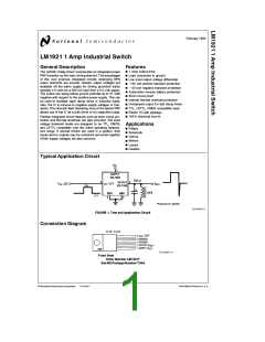
The LM1921 can be used alone as a simple relay or sole-
noid driver where a rapid decay of the load current is de-
sired, but the exact rate of decay is not critical to the sys-
tem. If the output is unclamped as in Figure 1, and the load
is inductive enough, the negative flyback transient will cause
the output of the IC to breakdown and behave similarly to a
zener clamp. Relying upon the IC breakdown is practical,
and will not damage or degrade the IC in any way. There are
two considerations that must be accounted for when the
driver is operated in this mode. The IC breakdown voltage is
process and lot dependent. Clamp voltages ranging from
b
b
60 to 120 volts (with respect to the supply voltage) will
FLYBACK RESPONSE
be encountered over time on different devices. This is not at
all critical in most applications. An important consideration,
however, is the additional heat dissipated in the IC as a
result. This must be added to normal device dissipation
when considering junction temperatures and heat sinking
requirements. Worst case for the additional dissipation can
be approximated as:
Since the 1921 is designed to drive inductive as well as any
other type of load, inductive kickback can be expected
whenever the output changes state from on to off (see
waveforms on Figure 1). The driver output was left un-
clamped since it is often desirable in many systems to
achieve a very rapid decay in the load current. In applica-
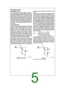
tions where this is not true, such as in Figure 2, a simple
external diode clamp will suffice. In this application, the inte-
grated current in the inductive load is controlled by varying
the duty cycle of the input to the driver IC. This technique
achieves response characteristics that are desirable for cer-
tain automotive transmission solenoids, for example.
2
e
Additional P
I
x L x f (Watts)
D
e
where:
I
peak solenoid current (Amps)
solenoid inductance (Henries)
maximum frequency input signal (Hz)
e
L
f
e
For solenoids where the inductance is less than ten milli-
henries, the additional power dissipation can be ignored.
For applications requiring a rapid controlled decay in the
solenoid current, such as fuel injector drivers, an external
zener and diode can be used as in Figure 3. The voltage
rating of the zener should be such that it breaks down be-
fore the output of the LM1921. The minimum output break-
Overshoot, undershoot, and ringing can occur on certain
loads. The simple solution is to lower the Q of the load by
the addition of a resistor in parallel or series with the load. A
value that draws one tenth of the current or DC voltage of
the load is usually sufficient.
b
down voltage of the IC output is rated at 57 volts with
respect to the supply voltage. Thus, on a 12 volt supply, the
TL/H/5271–10
TL/H/5271–11
FIGURE 3
FIGURE 2. Diode Clamp
Zener clamp for rapid controlled current decay
5

 NSC [ National Semiconductor ]