7.0 Package Specifications
The thermal characteristics and mechanical dimensions
for the Geode GXLV processor are provided on the
following pages.
These examples are given for reference only. The actual
value used for maximum power (P) and ambient tempera-
ture (TA) is determined by the system designer based on
system configuration, extremes of the operating environ-
ment, and whether active thermal management (via Sus-
pend Modulation) of the processor is employed.
7.1 THERMAL CHARACTERISTICS
Table 7-1 shows the junction-to-case thermal resistance
of the SPGA and BGA package and can be used to calcu-
late the junction (die) temperature under any given cir-
cumstance.
A maximum junction temperature is not specified since a
maximum case temperature is. Therefore, the following
equation can be used to calculate the maximum thermal
resistance required of the thermal solution for a given
maximum ambient temperature:
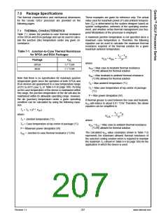
Table 7-1. Junction-to-Case Thermal Resistance
for SPGA and BGA Packages
T
– T
C
A
θ
+ θ
= ---------------------
CS
SA
Package
θ
J
C
P
where:
SPGA
BGA
1.7 °C/W
1.1 °C/W
θCS = Max case-to-heatsink thermal resistance
(°C/W) allowed for thermal solution
θSA = Max heatsink-to-ambient thermal resistance
(°C/W) allowed for thermal solution
Note that there is no specification for maximum junction
temperature given since the operation of both SPGA and
BGA devices are guaranteed to a case temperature range
of 0°C to 85°C (see TC in Table 6-4 on page 189). As long
as the case temperature of the device is maintained within
this range, the junction temperature of the die will also be
maintained within its allowable operating range. However,
the die (junction) temperature under a given operating
condition can be calculated by using the following equa-
tion:
TA = Max ambient temperature (°C)
TC = Max case temperature at top center of package
(°C)
P = Max power dissipation (W)
If thermal grease is used between the case and heatsink,
θCS will reduce to about 0.01 °C/W. Therefore, the above
equation can be simplified to:
TJ = TC + (P * θJC
where:
TJ = Junction temperature (°C)
C = Case temperature at top center of package (°C)
)
T
– T
C
A
θ
= ---------------------
CA
P
where:
T
θCA = θCS = Max case-to-ambient thermal resistance
(°C/W) allowed for thermal solution.
P = Maximum power dissipation (W)
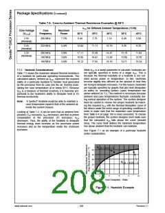
The calculated θCA value (examples shown in Table 7-2)
represents the maximum allowed thermal resistance of
the selected cooling solution which is required to maintain
the maximum TC (shown in Table 6-4 on page 189) for the
application in which the device is used.
θJ = Junction-to-case thermal resistance (°C/W)
C
Revision 1.1
207
www.national.com

 NSC [ National Semiconductor ]