SURFACE MOUNT ALUMINUM ELECTROLYTIC CAPACITORS
Low impedance, 105
C
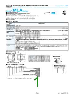
Low impedance, long life
Rated voltage 6.3 to 50V, Capacitance 10 to 1,000 F
@
@
@
@
Longer life
MLA
MVY
M
Case size 5 5.8L to 10 10L
F B
F
B
Suitable for applications requiring long life and low impedance such as
equipment in continuous operation, industrial applications, etc.
Solvent resistant type (see PRECAUTIONS AND GUIDELINES)
RoHS Compliant
@
@
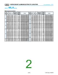
SPECIFICATIONS
?
Items
Characteristics
Category
Temperature Range
-40 to +105C
Rated Voltage Range
6.3 to 50Vdc
Capacitance Tolerance P20%(M)
(20C, 120Hz)
Leakage Current
I=0.01CV or 3MA, whichever is greater
Where, I : Max. leakage current (MA), C : Nominal capacitance (MF), V : Rated voltage (V)
(at 20C after 2 minutes)
Dissipation Factor
Rated voltage(Vdc
E61 to F61 0.28 0.24 0.22 0.16 0.13 0.12
tanE (Max.) F80
)
6.3V 10V 16V 25V 35V 50V
(tane)
0.32 0.27 0.24 0.16 0.13 0.12
0.24 0.22 0.16 0.13 0.12
6.3V 10V 16V 25V 35V 50V
HA0 to JA0
0.28
(20C, 120Hz)
Low Temperature
Characteristics
Rated voltage(Vdc)
Z(-25C)/Z(+20C)
Z(-40C)/Z(+20C)
4
3
7
2
5
2
3
2
3
2
3
(Max. impedance Ratio)
(120Hz)
10
Endurance
The following specifications shall be satisfied when the capacitors are restored to 20C after the rated voltage is applied for 3,000 hours
at 105C.
Capacitance change [P30% of the initial value
D.F. (tanE)
[300% of the initial specified value
[The initial specified value
Leakage current
Shelf life
The following specifications shall be satisfied when the capacitors are restored to 20C after exposing them for 1,000 hours at 105C without
voltage applied. Before the measurement, the capacitor shall be preconditioned by applying voltage according to Item 4.1 of JIS C 5101-4.
Capacitance change [P30% of the initial value
D.F. (tanE)
[300% of the initial specified value
[The initial specified value
Leakage current
DIMENSIONS [mm]
?
@Terminal Code : A
W
Size code
E61
D
5
L
A
B
C
W
P
MARKING
?
5.8 5.3 5.3 5.9 0.5 to 0.8 1.4
F61
F80
6.3 5.8 6.6 6.6 7.2 0.5 to 0.8 1.9
6.3 7.7 6.6 6.6 7.2 0.5 to 0.8 1.9
EX) 16V100MF
HA0
JA0
8
10.0 8.3 8.3 9.0 0.7 to 1.1 3.1
4R
0.3max.
LP0.3 (Note)
Note : LP0.5 for HA0 and JA0
AP0.2
10 10.0 10.3 10.3 11.0 0.7 to 1.1 4.5
100
CLA
PART NUMBERING SYSTEM
?
@Rated voltage symbol
1
2
3
4
5
6
7
8
9
10
11 12 13
14
15 16 17
18
Rated voltage (Vdc) Symbol
E M L A A A A A D A A A A M A A A G
6.3
10
j
Supplement code
Size code
Capacitance tolerance code
A
C
E
V
H
16
25
35
50
Capacitance code (ex. 10MF:100,100MF:101)
Taping code
Terminal code
Voltage code (ex. 6.3V:6R3,10V:100,50V:500)
Series code
Category
Please refer to "Product code guide (surface mount type)"
(1/2)
CAT. No. E1001K

 NPC [ NIPPON PRECISION CIRCUITS INC ]