Digital I/O Overview
Voltage Levels
For laboratory and test and measurement applications, the most
commonly used logic levels are 5 V TTL and TTL-compatible
CMOS. In industrial control applications, 24 V levels with isolation
are common and digital I/O devices may include electromagnetic
relays, motor controls, switches, valves, or pumps.
NI offers digital logic levels from nonisolated 5 V TTL/CMOS on
NI 650x devices, up to 28 V input and 60 V output on NI 6527
devices. NI 6527 devices also offer channel-to-channel optical
isolation and higher current switching capability on the outputs
(120 mA). For even higher voltage and isolation levels, the NI SCXI-1162,
SCXI-1162HV, and SCXI-1163 modules provide signal conditioning
from 5 V TTL/CMOS up to 240 VAC/VDC in optically isolated banks
of four lines each.
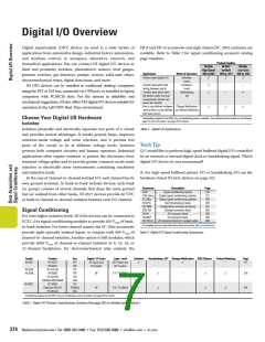
Figure 1. Test DIO device hardware and signal connections using
a Measurement & Automation Explorer test panel.
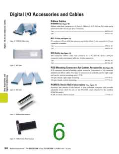
Connectivity
Software-Timed Digital I/O
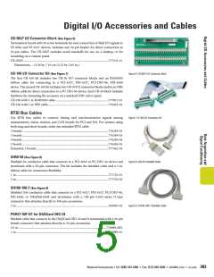
For shielded screw-terminal connections to your NI 6527 or NI 6508 Software-timed digital I/O, also referred to as unstrobed or static
device, use the SCB-100 connector block and shielded SH100-100-F digital I/O, implies that the writing to digital output lines and
cable. Unshielded connector blocks and cables are also available, such reading from digital input lines is performed by software
as the CB-100 kit which includes an unshielded ribbon cable. For command. A single write or read operation is performed with each
custom connectivity, the CA-1000 accessory enclosure can be used software command. Depending on the voltage and current
for convenient connection to pushbutton/rocker switches, banana requirements, you can use either NI 650x or NI 6527 software-
jack cables/probes, and LED indicators. Refer to Digital I/O timed devices to monitor and control switches, relays, actuators,
Accessories and Cables on page 382 for more details and options.
annunciators, fans, lights, and motors. The maximum speed for
software-timed digital I/O operations depends on the computer
processor speed, communication bus, and operating system. For
highest performance and greatest determinism in the timing of
your software-timed digital I/O, use a PXI system running
LabVIEW Real-Time.
Tech Tip
Q: I am controlling digital lines and relays, and I need to set the
power-up states of each line in software. Can I do this?
A: You can do this with the NI 6527 isolated digital I/O devices. You
can configure the power-up state of each output line independently
with a utility in the Developer Zone. For more information, see
page 377 or visit ni.com/info and enter ex95u3.
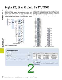
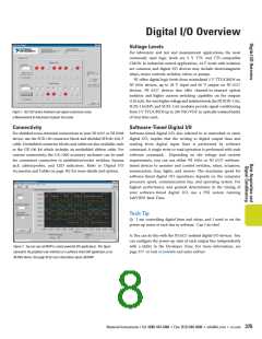
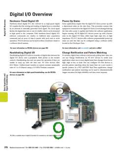
Figure 2. You can use LabVIEW to create powerful DIO applications. This figure
represents the graphical user interface of a software timed DIO application on an
NI 650x device. See page 43 for more information about LabVIEW.
National Instruments • Tel: (800) 433-3488 • Fax: (512) 683-9300 • info@ni.com • ni.com 375

 NI [ National Instruments ]