µPD75304B,75306B,75308B
★
3.5
PRECAUTIONS CONCERNING P00/INT4 PIN AND RESET PIN
In addition to the functions shown in 3.1 and 3.2, the P00/INT4 pin and RESET pin are also used to set the
test mode for testing internal µPD75308B operation (for IC testing).
The test mode is set when a voltage greater than VDD is applied to either of these pins. Consequently, if
noise exceeding VDD is applied during normal operation, the test mode may be entered, making it impossible
for normal operation to continue.
For example, misoperation may result if inter-wiring noise is applied to the P00/INT4 or RESET pin due to
the length of the wiring from these pins, and the pin voltage exceeds VDD.
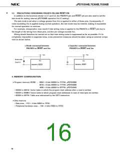
Wiring should therefore be carried out so that inter-wiring noise is suppressed as far as possible. If it is
completely impossible to suppress noise, noise prevention measures should be taken using an external compo-
nent as shown below.
o Diode connected between
o Capacitor connected between
P00/INT4 or RESET and VDD
P00/INT4 or RESET and VDD
VDD
VDD
Diode with
Small VF
VDD
VDD
P00/INT4, RESET
P00/INT4, RESET
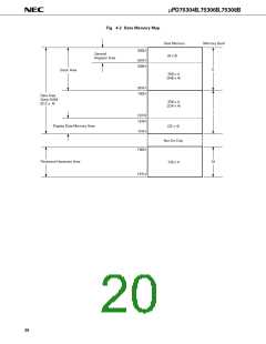
4. MEMORY CONFIGURATION
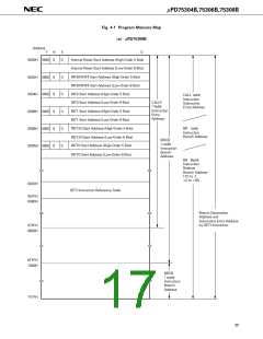
• Program memory (ROM) ... 8064 × 8 bits (0000H to 1F7FH): µPD75308B
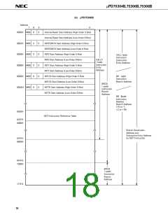
6016 × 8 bits (0000H to 177FH): µPD75306B
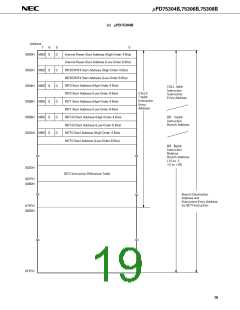
4096 × 8 bits (0000H to 0FFFH): µPD75304B
• 0000H to 0001H: Vector table in which the program start address after a reset is written.
• 0002H to 000BH: Vector table in which program start addresses in case of interrupts are written.
• 0020H to 007FH: Table area referenced by the GETI instruction.
• Data memory
• Data area ... 512 × 4 bits (000H to 1FFH)
• Peripheral hardware area ... 128 × 4 bits (F80H to FFFH)
16

 NEC [ NEC ]