CHAPTER 3 CPU FUNCTIONS
•
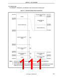
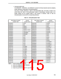
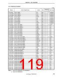
Interrupt/exception table
The V850ES/KF1, V850ES/KG1, and V850ES/KJ1 increase the interrupt response speed by assigning
handler addresses corresponding to interrupts/exceptions.
This group of handler addresses is called an interrupt/exception table. This table is located in the
internal ROM area. When an interrupt/exception request is acknowledged, execution jumps to the
handler address and the program written in that memory is executed. Table 3-3 lists the
interrupt/exception sources and the corresponding addresses.
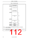
Table 3-3. Interrupt/Exception Table
Start Address of Interrupt/
Exception Table
Interrupt/
Start Address of Interrupt/
Exception Table
Interrupt/
Exception Source
Exception Source
00000000H
RESET
000001B0H
INTSRE1
00000010H
00000020H
00000030H
00000040H
00000050H
00000060H
00000080H
00000090H
000000A0H
000000B0H
000000C0H
000000D0H
000000E0H
000000F0H
00000100H
00000110H
00000120H
00000130H
00000140H
00000150H
00000160H
00000170H
00000180H
00000190H
000001A0H
NMI
000001C0H
000001D0H
000001E0H
000001F0H
00000200H
00000210H
00000220H
00000230H
00000240H
00000250H
00000260H
00000270H
00000280H
00000290H
000002A0H
000002B0H
000002C0H
000002D0H
000002E0H
000002F0H
00000300H
00000310H
00000320H
00000330H
00000340H
INTSR1
INTWDT1
INTWDT2
TRAP0n (n = 0 to F)
TRAP1n (n = 0 to F)
ILGOP/DBG0
INTWDTM1
INTP0
INTST1
INTTMH0
INTTMH1
INTCSIA0
INTIIC0Note 1
INTAD
INTKR
INTP1
INTWTI
INTP2
INTWT
INTP3
INTBRG
INTP4
INTTM020Note 2
INTTM021Note 2
INTTM030Note 2
INTTM031Note 2
INTCSIA1Note 2
INTTM040Note 3
INTTM041Note 3
INTTM050Note 3
INTTM051Note 3
INTCSI02Note 3
INTSRE2Note 3
INTSR2Note 3
INTST2Note 3
INTIIC1Note 4
INTP5
INTP6
INTTM000
INTTM001
INTTM010
INTTM011
INTTM50
INTTM51
INTCSI00
INTCSI01
INTSRE0
INTSR0
INTST0
Notes 1. Only for products with an I2C bus
2. Only for the V850ES/KG1 and V850ES/KJ1
3. Only for the V850ES/KJ1
4. Only for the µPD703216Y, 703217Y, and 70F3217Y
User’s Manual U15862EJ3V0UD
115

 NEC [ NEC ]