µPD6121, 6122
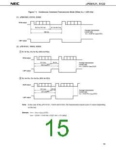
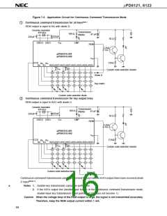
Figure 7-2. Application Circuit for Continuous Command Transmission Mode
1
Continuous command transmission for all keysNote 1
REM output is input to KI0 with diode D.
Ceramic resonator
Transmission
47 µF
+
-
455 kHz
100 Ω
display
220 pF
V
220 pF
82 Ω
OSCO OSCI
DD
LMP
REM
2.2kΩ
µPD6121G-001
µPD6121G-002
VSS
CCS
12kΩ
KI
2
KI
KI
0
KI
3
1
KI/O
0
KI/O
1
KI/O
2
KI/O
3
KI/O
4
KI/O
5
KI/O
6
KI/O
7
VDD
V
DD
Custom code selection resistor
Diode D
Key matrix
Custom code selection diode
2
Continuous command transmission for key output lines
REM output is input to KI/O with diode D.
Ceramic resonator
Transmission
455 kHz
+
-
100 Ω
47 µF
display
220 pF
220 pF
82 Ω
OSCO OSCI
V
DD
LMP
REM
2.2kΩ
µPD6121G-001
µPD6121G-002
V
SS
CCS
12 kΩ
KI
2
KI
KI
0
KI
3
1
KI/O
0
KI/O
1
KI/O
2
KI/O
3
KI/O
4
KI/O
5
KI/O
6
KI/O
7
V
DD
VDD
Custom code selection resistor
Custom code selection diode
Diode D
Continuous command transmission can be performed for keys whose KI/O output lines have received diode
D inputNote 2
.
Notes 1. Double-key transmission cannot be performed.
*
2. If the KI/O5 output line (double-input key) is in the continuous command transmission mode,
double-input key transmission is not performed (D5 does not become 1).
Caution When the voltage drop of the REM output is large, the signal is not transmitted accurately.
Therefore, keep the REM output current within 1 mA.
16

 NEC [ NEC ]