CHAPTER 17 µPD78F9436, 78F9456
17.1.4 Example of settings for Flashpro III (PG-FP3)
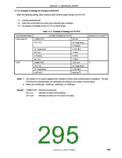
Make the following settings when writing to flash memory using Flashpro III (PG-FP3).
<1> Load the parameter file.
<2> Select the serial mode and serial clock using the type command.
<3> An example of settings for the PG-FP3 is shown below.
Table 17-4. Example of Settings for PG-FP3
Communication Mode
3-wire serial I/O
Example of Settings for PG-FP3
Number of V
0
PP PulsesNote 1
COMM PORT
CPU CLK
SIO-ch0
On Target Board
In Flashpro
4.1943 MHz
1.0 MHz
On Target Board
SIO CLK
In Flashpro
SIO CLK
4.0 MHz
1.0 MHz
UART
COMM PORT
CPU CLK
UART-ch0
On Target Board
4.1943 MHz
9600 bpsNote 2
8
On Target Board
UART BPS
Notes 1. The number of VPP pulses supplied from Flashpro III when serial communication is initialized. The pins
to be used for communication are determined according to the number of these pulses.
2. Select one of 9600 bps, 19200 bps, 38400 bps, or 76800 bps.
Remark COMM PORT: Selection of serial port
SIO CLK:
CPU CLK:
Selection of serial clock frequency
Selection of source of CPU clock to be input
User’s Manual U15075EJ1V0UM00
295

 NEC [ NEC ]