TX
mm inch
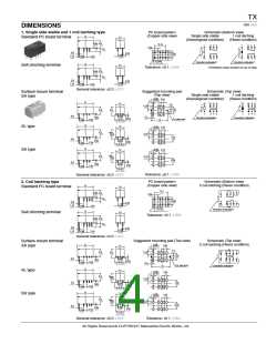
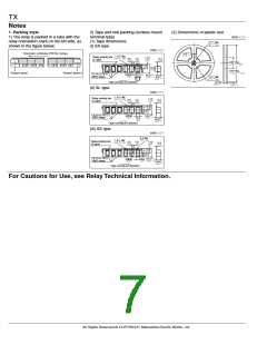
DIMENSIONS
PC board pattern
(Copper-side view)
Schematic (Bottom view)
1. Single side stable and 1 coil latching type
15
Single side stable
(Deenergized condition)
1 coil latching
(Reset condition)
Standard PC board terminal
7.4
.591
.291
0.65
8.2
10.16
.026
.323
1
3
4
5
1
3
4 5
.400
2.54
+
–
3.5
.100
.138
0.5
0.25
.010
5.08
.200
.020
5.08
.200
1.15
5.08
.200
2.54
.100
–
+
.045
12
10
9
8
12
10 9 8
8-1.0 dia
Direction indication*
Direction indication*
8-.039 dia
15
.591
7.4
Self clinching terminal
.291
Tolerance: 0.1 .004
*Orientation stripe located on top of relay.
0.65
8.2
.026
.323
3.5
.138
0.5
0.25
.010
.020
5.08
.200
1.15
5.08
.200
2.54
.100
.045
General tolerance: 0.3 .012
Suggested mounting pad
Schematic (Top view)
Surface-mount terminal
SA type
(Top view)
Single side stable
(Deenergized condition)
1 coil latching
(Reset condition)
5.08
.200
2.54
1
.100
.039
15
7.4
12 10
9
8
12
10
9
8
.591
1.6
.0.63
.291
–
+
3.16
.124
7.24
8.2
8.4
.285
.323
+
–
.331
1
3
4
5
1
3
4
5
5.08
0.5
0.3
0.65
.026
.020
Direction indication
Direction indication
.200
9.4 0.5
.370 .020
.012
0.25
.010
For glue-pad
2.54
.100
15
.591
5.08
.200
15
.591
7.4
5.08
.200
SL type
SS type
2.54
1
.291
.100
.039
8.2
Max.
10.0
.390
3.16
.124
.323
7.24
.285
0.5
5.08
0.65
.026
.020
0.25
.010
.200
9.4 0.5
.370 .020
2.54
.100
5.08
.200
15
.591
5.08
.200
7.4
2.54
.100
1
.291
.039
8.2
Max.
10.0
.390
2.16
.085
.323
6.24
.246
0.5
5.08
.200
0.65
.026
.020
0.25
.010
2.54
.100
5.08
.200
7.4 0.5
.291 .020
Tolerance: 0.1 .004
General tolerance: 0.3 .012
PC board pattern
(Copper side view)
Schematic (Bottom view)
2 coil latching (Reset condition)
2. Coil latching type
Standard PC board terminal
15
7.4
.591
.291
12.7
1
3
4
5
6
0.65
.500
2.54
8.2
.026
.323
.100
+
–
3.5
.138
5.08
.200
+
12
–
7
0.5
0.25
.010
.020
10
9
8
5.08
.200
1.15
5.08
.200
2.54
.100
.045
10-1.0 dia
Direction indication*
10-.039 dia
15
.591
7.4
Self clinching terminal
.291
Tolerance: 0.1 .004
0.65
8.2
.026
.323
3.5
.138
0.5
0.25
.010
.020
5.08
.200
1.15
5.08
.200
2.54
.100
.045
General tolerance: 0.3 .012
Suggested mounting pad (Top view)
Schematic (Top view)
2 coil latching (Reset condition)
Surface-mount terminal
SA type
5.08
15
2.54
1
7.4
.591
.100
.200
.039
.291
1.6
.0.63
12 10
9
8
7
–
–
6
8.2
3.16
.124
8.4
.323
.331
+
+
7.24
.285
5.08
0.5
0.65
.026
.020
.200
9.4 0.5
.370 .020
1
3
4
5
0.25
.010
2.54
.100
5.08
.200
0.3
.012
For glue-pad
Direction indication
15
.591
15
.591
7.4
SL type
SS type
5.08
.200
.291
2.54
1
.100
.039
8.2
Max.
10.0
.390
.323
3.16
.124
0.5
7.24
.285
5.08
0.65
.026
.020
0.25
.010
.200
9.4 0.5
.370 .020
2.54
.100
5.08
.200
15
.591
7.4
5.08
.200
2.54
.100
.291
1
.039
8.2
Max.
10.0
.390
2.16
.085
.323
6.24
.285
0.5
5.08
.200
0.65
.026
.020
0.25
.010
2.54
.100
5.08
.200
7.4 0.5
.291 .020
General tolerance: 0.3 .012
Tolerance: 0.1 .004
All Rights Reserved © COPYRIGHT Matsushita Electric Works, Ltd.

 NAIS [ NAIS(MATSUSHITA ELECTRIC WORKS) ]