HE
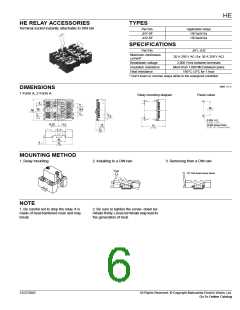
HE RELAY ACCESSORIES
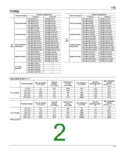
TYPES
Terminal socket instantly attachable to DIN rail
Part No.
Applicable relays
HE1a/JH1a
JH1-SF
JH2-SF
HE2a/JH2a
SPECIFICATIONS
Part No.
JH1, JH2
Maximum continuous
current*
20 A 250 V AC (1a: 30 A 250 V AC)
Breakdown voltage
Insulation resistance
Heat resistance
2,000 Vrms between terminals
More than 1,000 MΩ between poles
150°C ±3°C for 1 hour
* Don't insert or remove relays while in the energized condition.
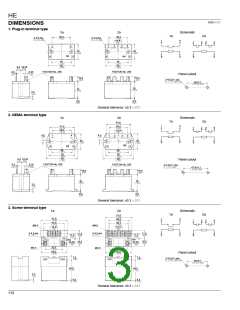
mm inch
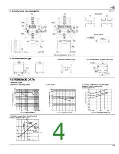
DIMENSIONS
1 Form A, 2 Form A
Relay mounting diagram
Panel cutout
6
8
1
2
9
.354
11
.433
40
22
14.4
1.575
60
.866
.567
2.362
11
3
4
7
5
.433
9.2
.362
9
.354
2-DIA. 4.2
2-DIA. .165
10.25
.404
8.4
.331
16
(2-M4 Screw hole)
(2-M.157 Screw hole)
61
.630
2.402
23
.906
34
1.339
70
4
.157
2.756
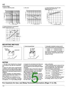
MOUNTING METHOD
1. Relay mounting
2. Installing to a DIN rain
3. Removing from a DIN rain
Push
Flat-head screw driver
NOTE
1. Be careful not to drop the relay. It is
made of heat-hardened resin and may
break.
2. Be sure to tighten the screw- down ter-
minals firmly.Loose terminals may lead to
the generation of heat.
12/27/2002
All Rights Reserved, © Copyright Matsushita Electric Works, Ltd.
115
Go To Online Catalog

 NAIS [ NAIS(MATSUSHITA ELECTRIC WORKS) ]