AQ-H
CAUTIONS FOR USE
1. For cautions regarding use, please
refer to ’03-’04 Solid State Relays
catalog.
6. Cleaning
(2) Vapor phase soldering method
The solid state relay forms an optical path
by coupling a light-emitting diode (LED)
and photodiode via transparent silicon
resin.
For this reason, avoid ultrasonic cleansing
if at all possible.
We recommend cleaning with an organic
solvent. If you cannot avoid using
ultrasonic cleansing, please ensure that
the following conditions are met, and
check beforehand for defects.
• Frequency: 27 to 29 kHz
T2
T1
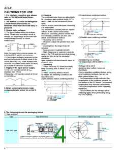
2.The internal IC could be damaged if
a short forms between the I/O
terminals while the solid state relay is
powered.
t1
t2
3. Output spike voltages
T1 = 180 to 200°C 366 to 392°F
T2 = 215°C 419°F or less
t1 = 40 s
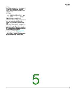
1) The figure below shows an ordinary
circuit. Please add a snubber circuit or
varistor, as noise/surge on the load side
could damage the unit or cause
malfunctions.
t2 = 90 s or less (40 s: SOP type)
(3) Double wave soldering method
T2
• Ultrasonic output: No greater than 0.25
W/cm2
• Cleaning time: No longer than 30
seconds
1
2
3
4
8
Load
T1
VL(AC)
6
5
• Cleanser used: Asahiklin AK-225
• Other: Submerge in solvent in order to
prevent the PCB and elements from being
contacted directly by the ultrasonic
vibrations.
t1
t2
t3
Note) Connection of an external resister, etc.,
to terminal No. 5 (gate) is not necessary.
T1 = 155 to 165°C 311 to 329°F
T2 = 260°C 500°F or less
t1 = 60 s or less
t2+t3 = 5 s or less
2) Even if spike voltages generated at the
load are limited with a clamp diode if the
circuit wires are long, spike voltages will
occur by inductance. Keep wires as short
as possible to minimize inductance.
(4) Soldering iron method
Tip temperature: 280 to 300°C 536 to
572°F
Wattage: 30 to 60 W
Soldering time: within 5 seconds
(5) Others
Check mounting conditions before using
other soldering methods (hot-air, hot
plate, pulse heater, etc.)
Note: Applies to unit area ultrasonic output for
ultrasonic baths.
7. Soldering
1) When soldering PC board terminals,
keep soldering time to within 10 s at
260°C 500°F.
2) When soldering surface-mount
terminals, the following conditions are
recommended.
4. Ripple in the input power supply
1) For LED operate current at Emin,
maintain min. 10 mA
2) Keep the LED operate current at 50 mA
or less at Emax.
• The temperature profile indicates the
temperature of the soldered terminal on
the surface of the PC board.The ambient
temperature may increase excessively.
Check the temperature under mounting
conditions.
• The conditions for the infrared reflow
soldering apply when preheating using
the VPS method.
(1) IR (Infrared reflow) soldering method
T3
T2
T1
Emin.
Emax.
5. When soldering terminals, keep
soldering time to within 10s at 260°C
500°F
t1
t2
T1 = 155 to 165°C 311 to 329°F
T2 = 180°C 200°C 356 to 392°F
T3 = 245°C 473°F or less
t1 = 120 s or less
t2 = 30 s or less
8.The following shows the packaging format
mm inch
1) Tape and reel
Type
Tape dimensions
Dimensions of paper tape reel
21±0.8
.827±.031
Direction of picking
4±0.1 10.1±0.1
.157±.004 .400±.004
80±1 dia.
3.150±.039 dia.
Tractor feed holes
1.5+–00.1 dia.
.059+–0.004dia.
1.75±0.1
0.3±0.05
.012±.002
.069±.004
2±0.5
.079±.020
7.5±0.1
300±2 dia.
11.811±.079 dia.
.295±.004
16±0.3
.630±.012
80±1 dia.
3.150±.039 dia.
Device mounted
on tape
8-pin SMD type
10.2±0.1
12±0.1
.472±.004
2±0.1
.079±.004
.402±.004
4.5±0.3
.177±.012
1.55±0.1 dia.
.061±.004 dia.
(1) When picked from 1/2/3/4-pin side: Part No. AQH❍❍❍❍AX (Shown above)
(2) When picked from 5/6/8-pin side: Part No. AQH❍❍❍❍AZ
13±0.5 dia.
.512±.020 dia.
17.5±2.0
2±0.5
.689±.079
.079±.020
4

 NAIS [ NAIS(MATSUSHITA ELECTRIC WORKS) ]