CT
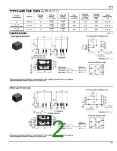
3. Slim 1c type
mm inch
PC board pattern (Bottom view)
17.4
.685
7.2
.283
3-1.4 dia.
3-.055 dia.
9.5
13.5
.531
.374
6
0.4
.016
Max. 1.0
.039
.236
4.3
.169
3.15
.124
3.5
.138
2-1.1 +0.1 dia.
*A
0
0.65
.026
2-.043 +0.04 dia.
15
.591
0
0.4
.016
0.8
.031
1
.039
1
.039
0.4
0.4
0.3
.012
Sealed by epoxy resin
.016 .016
Tolerance: ±0.1±.004
9.5
.374
1.25
.049
Pre-soldering
6
.236
Schematic (Bottom view)
1
.039
4.3
.169
Dimension:
Max. 1mm .039 inch:
1 to 3mm .039 to .118 inch: ±0.2 ± .008
Min. 3mm .118 inch: ±0.3 ± .012
Tolerance
±0.1 ± .004
3.15
.124
JAPAN
NO
COIL
NC
COM
1.45
.057
0.65
.006
15
.591
* Dimensions (thickness and width) of terminal specified in this catalog is measured before pre-soldering.
Intervals between terminals is measured at A surface level.
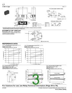
EXAMPLE OF CIRCUIT
NO
Forward/reverse control circuits of DC
COM
12 V DC
motor for power windows
Tr 1
NC
M
NO
NC
COM
Tr 2
M Power window motor
REFERENCE DATA
1-(1). Coil temperature rise (at 20°C 68°F)
1-(2). Coil temperature rise (at 85°C 185°F)
Sample: ACT212, 3pcs
Sample: ACT212, 3pcs
Contact carrying current: 0A, 10A, 20A
Contact carrying current: 0A, 10A, 20A
140
140
20A
120
120
20A
10A
0A
100
100
10A
0A
80
80
60
60
40
20
0
40
20
0
12
14
16
12
14
16
Coil applied voltage, V
Coil applied voltage, V
2-(1). Electrical life test (Motor load)
2-(2). Electrical life test (Motor lock)
Tested sample: ACT212, 3pcs.
Load: 5A steady, Inrush 25A, 14V DC
Operating frequency: ON 0.5s, OFF 9.5s
Tested sample: ACT212, 3pcs.
Load: 25A, 14V DC
Operating frequency: ON 0.5s, OFF 9.5s
10
10
8
Circuit
8
Tested sample
Max.
X
Min.
Pick-up voltage
Drop-out voltage
Pick-up voltage
Max.
X
Min.
6
6
4
4
M
Drop-out voltage
Max.
X
Min.
Max.
X
Min.
2
2
0
0
0
10
0
10
20
4
4
No. of operations, × 10
No. of operations, × 10
For Cautions for use, see Relay Technical Information (Page 48 to 76).
366
9/1/2000
All Rights Reserved, © Copyright Matsushita Electric Works, Ltd.
Go To Online Catalog

 NAIS [ NAIS(MATSUSHITA ELECTRIC WORKS) ]