• This PDF catalog is downloaded from the website of Murata Manufacturing co., ltd. Therefore, it’s specifications are subject to change or our products in it may be discontinued without advance notice. Please check with our
• Please read rating and !CAUTION (for storage, operating, rating, soldering, mounting and handling) in this catalog to prevent smoking and/or burning, etc.
!Note
!Note
C02E.pdf
sales representatives or product engineers before ordering.
• This catalog has only typical specifications because there is no space for detailed specifications. Therefore, please approve our product specifications or transact the approval sheet for product specifications before ordering0. 9.9.18
• This PDF catalog has only typical specifications because there is no space for detailed specifications. Therefore, please approve our product specifications or transact the approval sheet for product specifications before ordering.
GNM Series Specifications and Test Methods (2)
GNM Series Specifications and Test Methods (2)
In case Non "*" is added in PNs table, please refer to GNM Series Specifications and Test Methods (1).
In case "*" is added in PNs table, please refer to GNM Series Specifications and Test Methods (2).
Continued from the preceding page.
No.
Item
Specifications
Test Method
2
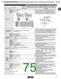
Appearance No marking defects
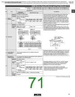
Solder the capacitor to the test jig (glass epoxy board) shown in
Fig. 2 using a eutectic solder. Then apply a force in the
direction shown in Fig. 3. The soldering should be done by the
reflow method and should be conducted with care so that the
soldering is uniform and free of defects such as heat shock.
Capacitance
Change
Within ±10%
#GNMpp4
#GNMpp2
20
Pressurizing
50
100
1.0
100
1.0
speed : 1.0mm/sec.
Pressurize
5.0
a
b
5.0
a
b
R230
12 Deflection
c
c
d
Thickness: 0.8mm
d
Flexure : V1
Type
a
b
c
d
GNM0M2
GNM1M2
GNM212
GNM214
GNM314
2.0±0.05 0.2±0.05 0.2±0.05 0.25±0.05
2.0±0.05 0.5±0.05 0.32±0.05 0.32±0.05
2.0±0.05 0.6±0.05 0.5±0.05 0.5±0.05
2.0±0.05 0.7±0.05 0.3±0.05 0.2±0.05
2.5±0.05 0.8±0.05 0.4±0.05 0.4±0.05
Capacitance meter
45 45
Fig. 3
(in mm)
Fig. 2
Immerse the capacitor in a solution of ethanol (JIS-K-8101) and
rosin (JIS-K-5902) (25% rosin in weight proportion). Preheat at
80 to 120°C for 10 to 30 seconds. After preheating, immerse in
eutectic solder solution for 2±0.5 seconds at 230±5°C or
Sn-3.0Ag-0.5Cu solder solution for 2±0.5 seconds at 245±5°C.
Solderability of
Termination
75% of the terminations are to be soldered evenly
and continuously.
13
Appearance No marking defects
Capacitance R6*4: Within ±7.5%
Preheat the capacitor at 120 to 150°C for 1 minute. Immerse
the capacitor in a eutectic solder or Sn-3.0Ag-0.5Cu solder
solution at 270±5°C for 10±0.5 seconds.
Let sit at room temperature for 24±2 hours, then measure.
• Initial measurement
Perform a heat treatment at 150 +0/-10°C for one hour and
then let sit for 24±2 hours at room temperature. Perform
the initial measurement.
Change
*4 GNM0M2R60E105: Within +15/-7.5%
Resistance
0.1 max. *3
14 to Soldering D.F.
*3 However 0.125 max. about Table 3 items.
Heat
I.R.
50Ω · F min.
Dielectric
Strength
No failure
Appearance No marking defects
Capacitance R6*5: Within ±12.5%
Fix the capacitor to the supporting jig in the same manner and
under the same conditions as (10).
Perform the five cycles according to the four heat treatments
listed in the following table.
Change
D.F.
I.R.
*5 GNM0M2R60E105: Within ±15%
0.1 max. *3
Let sit for 24±2 hours at room temperature, then measure.
*3 However 0.125 max. about Table 3 items.
Step
1
2
3
4
Temperature
Cycle
15
Min. Operating Room Min. Operating Room
50Ω · F min.
Temp. (°C)
Time (min.)
Temp.
Temp.
Temp.
Temp.
30±3
2 to 3
30±3
2 to 3
• Initial measurement
Dielectric
Strength
No failure
Perform a heat treatment at 150 +0/-10 °C for one hour and
then let sit for 24±2 hours at room temperature.
Perform the initial measurement.
Appearance No marking defects
Apply the rated voltage at 40±2°C and 90 to 95% humidity for
500±12 hours. The charge/discharge current is less than 50mA.
• Initial measurement
Perform a heat treatment at 150 +0/-10°C for one hour
and then let sit for 24±2 hours at room temperature.
Perform the initial measurement.
Capacitance
R6: Within ±12.5%
Change
High
Temperature
16 High
Humidity
D.F.
I.R.
0.2 max.
• Measurement after test
(Steady)
Perform a heat treatment at 150 +0/-10°C for one hour
and then let sit for 24±2 hours at room temperature, then
measure.
12.5Ω · F min.
Appearance No marking defects
Apply 150% (GNM1M2R61A225/1C105: 125% of the rated
voltage) of the rated voltage for 1000±12 hours at the
maximum operating temperature ±3°C. Let sit for 24±2 hours
at room temperature, then measure.
Capacitance
R6: Within ±12.5%
Change
D.F.
I.R.
0.2 max.
The charge/discharge current is less than 50mA.
• Initial measurement
Perform a heat treatment at 150 +0/-10°C for one hour
and then let sit for 24±2 hours at room temperature.
Perform the initial measurement.
17 Durability
25Ω · F min.
• Measurement after test
Perform a heat treatment at 150 +0/-10°C for one hour and
then let sit for 24±2 hours at room temperature, then measure.
73

 MURATA [ muRata ]