• This PDF catalog is downloaded from the website of Murata Manufacturing co., ltd. Therefore, it’s specifications are subject to change or our products in it may be discontinued without advance notice. Please check with our
• Please read rating and !CAUTION (for storage, operating, rating, soldering, mounting and handling) in this catalog to prevent smoking and/or burning, etc.
!Note
!Note
C02E.pdf
sales representatives or product engineers before ordering.
• This catalog has only typical specifications because there is no space for detailed specifications. Therefore, please approve our product specifications or transact the approval sheet for product specifications before ordering0. 9.9.18
• This PDF catalog has only typical specifications because there is no space for detailed specifications. Therefore, please approve our product specifications or transact the approval sheet for product specifications before ordering.
Package
Continued from the preceding page.
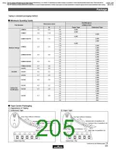
(4) Taping Method
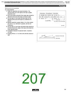
q Tapes for capacitors are wound clockwise. The
sprocket holes are to the right as the tape is pulled
Vacant section Chip mounting unit Vacant section
toward the user.
w Part of the leader and part of the empty tape should be
attached to the end of the tape as shown at right.
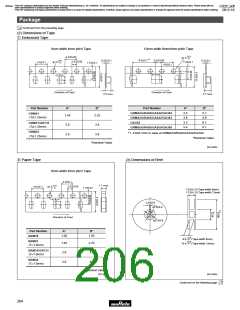
e The top tape or cover tape and base tape are not
160 min.
160 min.
400 to 560
(Top Tape or Cover Tape alone)
attached at the end of the tape for a minimum of 5
pitches.
Direction of feed
r Missing capacitors number within 0.1% of the number
per reel or 1 pc, whichever is greater, and are not
continuous.
(in mm)
t The top tape or cover tape and bottom tape should not
protrude beyond the edges of the tape and should not
cover sprocket holes.
y Cumulative tolerance of sprocket holes, 10 pitches:
T0.3mm.
u Peeling off force: 0.1 to 0.6N in the direction shown at
right.
Top Tape or Cover Tape
Base Tape
18
205

 MURATA [ muRata ]