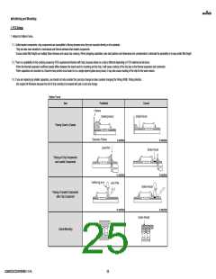
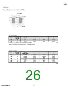
2. Land Dimensions
Please confirm the suitable land dimension by evaluating of the actual SET / PCB.
Table 1 Flow Soldering Method
Chip Dimension
Series
Chip(L×W)
a
b
c
(L/W) Code
GQM
GQM
18
21
1.6×0.8
2.0×1.25
0.6 to 1.0
1.0 to 1.2
0.8 to 0.9
0.9 to 1.0
0.6 to 0.8
0.8 to 1.1
Flow soldering can only be used for products with a chip size of 1.6x0.8mm to 2.0x1.25mm.
(in mm)
Resistance to PCB bending stress may be improved by designing the “a” dimension with solder resist.
Table 2 Reflow Soldering Method
Chip Dimension
(L/W) Code
Chip(L×W)
(Dimensions Tolerance)
0.6×0.3(±0.03)
1.0×0.5(±0.05)
1.6×0.8(±0.10)
1.6×0.8(±0.15)
2.0×1.25
Series
a
b
c
GQM
GQM
03
15
0.2 to 0.25
0.3 to 0.5
0.6 to 0.8
0.7 to 0.9
1.0 to 1.2
2.2 to 2.5
0.2 to 0.3
0.35 to 0.45
0.6 to 0.7
0.7 to 0.8
0.6 to 0.7
0.8 to 1.0
0.25 to 0.35
0.4 to 0.6
0.6 to 0.8
0.8 to 1.0
0.8 to 1.1
1.9 to 2.3
GQM
18
GQM
GQM
21
22
2.8×2.8
(in mm)
GQM0335C2D9R2WB01-01A
26

 MURATA [ muRata ]