! Caution
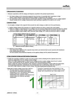
4-1.Reflow Soldering
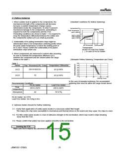
1. When sudden heat is applied to the components, the
mechanical strength of the components will decrease
because a sudden temperature change causes
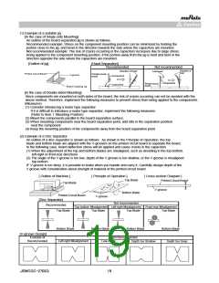
[Standard Conditions for Reflow Soldering]
deformation inside the components. In order to prevent
mechanical damage to the components, preheating is
required for both the components and the PCB.
Temperature(℃)
Soldering
Peak Temperature
Gradual
Cooling
(200℃)
220℃
Preheating conditions are shown in table 1. It is required to
keep the temperature differential between the solder and
the components surface (ΔT) as small as possible.
ΔT
(170℃)
(150℃)
(130℃)
190℃
170℃
150℃
Preheating
2. Solderability of tin plating termination chips might be
deteriorated when a low temperature soldering profile where
the peak solder temperature is below the melting point of
tin is used. Please confirm the solderability of tin plated
termination chips before use.
Time
60-120 seconds 30-60 seconds
Temperature
Incase of Lead Free Solder
( ): In case of Pb-Sn Solder
3. When components are immersed in solvent after mounting,
be sure to maintain the temperature difference (ΔT)
between the component and the solvent within the range
shown in the table 1.
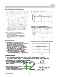
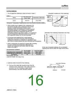
[Allowable Reflow Soldering Temperature and Time]
280
270
260
Table 1
Temperature Differential
Series
ChipꢀDimension(L/W)ꢀCode
03/15/18/21/31
GC□
ΔT≦190℃
250
240
230
220
32
GC□
ΔT≦130℃
0
30
60
90
120
Soldering Time(s)
ꢀꢀꢀꢀꢀꢀꢀꢀIn the case of repeated soldering, the accumulated
ꢀꢀꢀꢀꢀꢀꢀꢀsoldering time must be within the range shown above.
Lead Free Solder
Recommended Conditions
Pb-Sn Solder
Peak
Temperature
230 to 250℃
240 to 260℃
Air or N2
Atmosphere
Air
Pb-Sn Solder: Sn-37Pb
Lead Free Solder: Sn-3.0Ag-0.5Cu
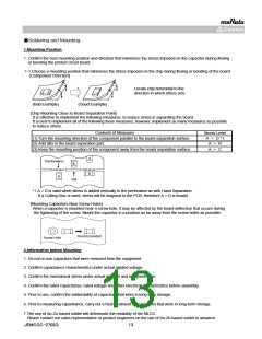
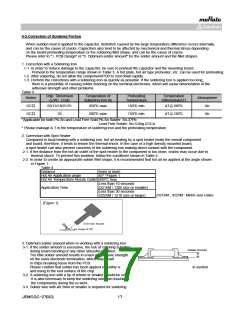
4. Optimum Solder Amount for Reflow Soldering
4-1. Overly thick application of solder paste results in a excessive solder fillet height.
This makes the chip more susceptible to mechanical and thermal stress on the board and may cause the chips to crack.
4-2. Too little solder paste results in a lack of adhesive strength on the termination, which may result in chips breaking
loose from the PCB.
4-3. Please confirm that solder has been applied smoothly to the termination.
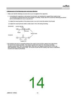
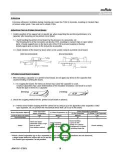
Inverting the PCB
Make sure not to impose any abnormal mechanical shocks to the PCB.
JEMCGC-2702Q
15

 MURATA [ muRata ]