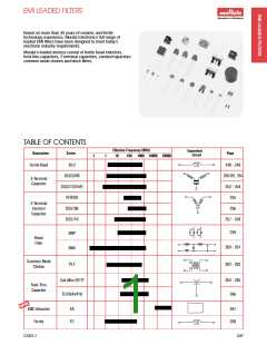
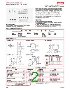
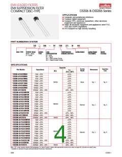
EMI LEADED FILTERS
FERRITE BEAD INDUCTORS
BL01, BL02 & BL03 Series
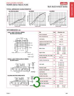
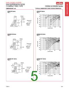
TYPICAL IMPEDANCE CHARACTERISTICS
BL01RN1/BL02RN1
BL02RN2
BL03RN2
140
140
120
100
80
140
120
100
120
100
80
Z
R
80
60
Z
Z
60
60
R
X
R
X
40
20
0
40
20
0
40
X
20
0
0.5
1
2
5
10 20
50 100 200 500 1000
0.5
1
2
5
10 20
50 100 200 500 1000
0.5
1
2
5
10 20
50 100 200 500 1000
Frequency (MHz)
Frequency (MHz)
Frequency (MHz)
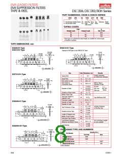
TAPE DIMENSIONS: mm
Item
Code
Dimensions: mm
AXIAL LEAD TYPE BL01 SERIES
BL01RN1-A62T5/A63T6
Pitch of Component
P
12.7
Pitch of Sprocket Hole
P0
12.7 0.2
5.0 ± 0.3
3.6 ± 0.15
0.6 ± 0.05
+0.8
5.0
Lead Spacing
F
–0.2
0
Length from Hole Center to Lead
P1
P2
3.85 0.7
6.35 1.3
5.0 ± 0.5
1.2 max.
Length from Hole Center to
Component Center
BL02RN1
7.5 max.
9.0 max.
8.3 max.
3.2 max.
Width of Body
Height of Bead
D
H
BL02RN2
BL03RN2
L1
L1 – L2 ꢁ 1.5
L2
BL02
BL03
7.5 max.
6.5 max.
0.8 max.
6.0 ± 1.0
* *
+2
–1
** A62T5 = 52
** A63T6 = 26
Deviation along Tape, Left or Right ꢀS
1.0
+1.5
–0
Carrier Tape Width
W
18.0 0.5
RADIAL LEAD TYPE BL02/BL03 SERIES
BL02RN1-R62T4
+0
Position of Sprocket Hole
W1
9.0
–0.5
ꢀS
T2= 16.5 0.5
T3= 20.0 0.5
T4= 18.5 0.5
P2
P
D
H
T
Lead Length
H1
P1
F
W2
d
ꢀh
Protrusion Length
ꢀ
D0
d
+0.5 to –1.0
4.0 0.1
0.60 0.5
0.7 0.2
1.0 max.
H1
L
W1
D0
W0
W
Diameter of Sprocket Hole
Lead Diameter
ꢀ
t
P0
Total Tape Thickness
Deviation Across Tape
t
BL02RN2-R62T4/BL03RN2-R62T4
ꢀh
ꢀS
P2
P
D
T
H
+0
11.0
Portion to Cut in Case of Defect
L
–1.0
P1
F
W2
d
Hold Down Tape Width
Hold Down Tape Position
W0
W2
12.0 0.5
1.5 1.5
ꢀh
H1
L
W1
D0
W0
W
ꢀ
BL02
BL03
3.4 0.2
2.3 max.
t
P0
Body Thickness
T
CG01-I
249

 MURATA [ muRata ]