EMI LEADED FILTERS
EMI SUPPRESSION FILTERS
BLOCK FILTERS
BNX002/003/005 Series
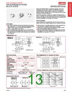
Block-type BNX002 filters completely eliminate noise from
extremely wide frequency bands. The BNX002 is perfect
for use in DC power circuits and is designed to perform
superbly—through the use of through-type barrier layer
capacitors, monolithic chip capacitors and bead inductors.
Each block contains a number of compact EMI suppression
filters. In addition, the input/output terminals and the grounding
terminal are aligned in the same direction, thus permitting fast
and easy assembly on any type of PC board.
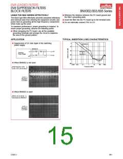
APPLICATIONS
Noise elimination from signal lines and DC power sources in a
variety of switching power sources, engine control units, digital
equipment and computer terminals.
FEATURES
ꢀꢀThe BNX002 incorporates feed-thru-type barrier layer
capacitor and a chip capacitor which are interconnected.
This combination enables the BNX002 to achieve a
significantly large insertion loss throughout the extremely
wide frequency range of 0.5MHz to 1GHz, which covers
the AM and UHF-TV broadcast frequency bands.
ꢀꢀThe filter is extremely compact since only one filter block
is needed to completely eliminate noise from both the
positive and ground lines.
ꢀꢀThere are no connections in the feed-thru current circuits,
thus ensuring highly reliable performance.
ꢀꢀBoth the input/output terminals and the grounding terminal
are aligned in the same direction, permitting fast and easy
installation on any type of PC board.
ꢀꢀNon polarized—but care must be taken to ensure that
terminal with inductor on ground line faces EMI source.
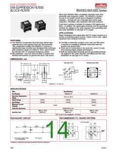
DIMENSIONS: mm
Top View PCB
Bottom View Filter
12.0 ± 0.5
11.0 ± 0.5
1.2 D.x6
PSG
CG
B
13.0 max.*
2.5 ± 0.1
2.5 ± 0.1
B
PSG
CG
CG
CG
CG
18.0*
max.
CB
CG
CB
2.5 ± 0.1
3.5 ±1.0
0.8 D.
5.0 ± 0.5
5.0 ± 0.1
7.5 ± 0.1
0.6 ± 0.1
For 005/01
Lead Dia. is
1.0
2.5 ± 0.2
2.5 ± 0.2
7.5 ± 0.2
*BNX005-01 = 13.5 and 18.5
SPECIFICATIONS
Item
Specifications
ꢀ
ꢀ
ꢀ
Part Number
BNX002-01
BNX003-01
BNX005-01
Operating Temperature
Range
–30°C to +85°C
Rated Voltage
Test Voltage
50VDC
125VDC
150VDC
375VDC
50VDC
125VDC
Maximum Current
Capacity
10ADC
15ADC
Insulation Resistance
1000M Ohms min.
1MHz to 1GHz
40dB min.
5MHz to 1GHz
40dB min.
1MHz to 1GHz
40dB min.
Insertion Loss
20°C to 25°C Line Impedance = 50 Ohms
EQUIVALENT CIRCUIT
RECOMMENDED P.C. BOARD PATTERN
TOP VIEW
BOTTOM VIEW
PSG
B
B
PSG
L1
L3
C2
B
CB
CG
C1
PSG
B
Ground
Plane
L2
PSG
CG
CG
CB
CG
CG
CG
CG
CB
PSG: Power Supply Ground
CG: Circuit Ground
CB: Circuit B
ꢀ
Available as standard through authorized Murata Electronics Distributors.
260
CG01-I

 MURATA [ muRata ]