MP6922—DUAL FAST TURN-OFF INTELLIGENT CONTROLLER
stops switching. The part will return to normal
low after about 20ns turn off delay (defined in
Fig.4) by the control circuitry. Similar with turn-on
phase, a 1.6us blanking time is added after the
switch is turned off, during which the MOSFET is
never turned on to avoid error trigger.
operation after the junction temperature has
dropped to 120oC.
Turn-on Phase
When the switch current flows through the body
diode of the MOSFET, there will be a negative
VDS (VD-VSS) across it (<-500mV), the VDS is
much lower than the turn on threshold of the
control circuitry (-70mV), which then turns on the
MOSFET after 200ns turn-on delay (defined in
Fig.2).
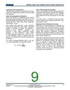
Fig.3 show the MP6922 operation at heavy load
condition. Due to the high current, the driver
voltage will be saturated at first. After VDS goes to
above -70mV, driver voltage decreases to adjust
the VDS to typical -70mV.
Fig.4 show the MP6922 operation at light load
condition. Due to the low current, the driver
voltage never saturates but begins to decrease
as soon as the synchronous power switch is
turned on and adjust the VDS.
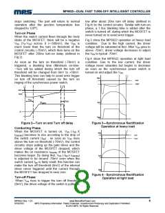
As soon as the turn on threshold (-70mV) is
triggered, a blanking time (Minimum on-time:
~1us) will be added during which the turn off
threshold will be changed from 0mV to +50mV.
This blanking time can help to avoid error trigger
on turn off threshold caused by the turn on
ringing of the synchronous power switch.
Vds
0mV
-70mV
0mV
-70mV
VDS
tDon
tDoff
Isd
VGATE
2V
Vgs
Figure 2—Turn on and Turn off delay
Conducting Phase
Figure 3—Synchronous Rectification
Operation at heavy load
When the MOSFET is turned on, VDS (-ISD
X
Vds
0mV
r
DS(ON)) becomes to rise according to the drop of
-70mV
the switch current (ISD) , as soon as VDS rises
above the turn on threshold (-70mV), the control
circuitry stops pulling up the gate driver and the
driver voltage of the MOSFET dropped, which
makes the on resistance rDS(ON) of the MOSFET
becomes larger. By doing that, VDS (-ISD x rDS(ON)
)
Isd
is adjusted to be around -70mV even when the
switch current ISD is fairly small, this function can
make the turn off threshold (0mV) of the internal
driver never triggered until the current through
the MOSFET has dropped to near zero.
Vgs
Figure 4—Synchronous Rectification
Turn-off Phase
When VDS rises to trigger the turn off threshold
(0mV), the driver voltage of the switch is pulled to
Operation at light load
MP6922 Rev. 1.23
9/19/2012
www.MonolithicPower.com
MPS Proprietary Information. Patent Protected. Unauthorized Photocopy and Duplication Prohibited.
© 2012 MPS. All Rights Reserved.
8

 MPS [ MONOLITHIC POWER SYSTEMS ]