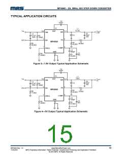
MP4560 – 2A, 2MHz, 55V STEP-DOWN CONVERTER
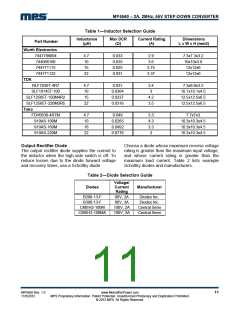
Table 1—Inductor Selection Guide
Inductance Max DCR Current Rating
Dimensions
L x W x H (mm3)
Part Number
(µH) (Ω) (A)
Wurth Electronics
7447789004
4.7
10
15
22
0.033
0.035
0.025
0.031
2.9
3.6
7.3x7.3x3.2
10x10x3.8
12x12x6
744066100
744771115
3.75
3.37
744771122
12x12x6
TDK
RLF7030T-4R7
SLF10145T-100
SLF12565T-150M4R2
SLF12565T-220M3R5
Toko
4.7
10
15
22
0.031
0.0364
0.0237
0.0316
3.4
3
7.3x6.8x3.2
10.1x10.1x4.5
12.5x12.5x6.5
12.5x12.5x6.5
4.2
3.5
FDV0630-4R7M
919AS-100M
919AS-160M
919AS-220M
4.7
10
16
22
0.049
0.0265
0.0492
0.0776
3.3
4.3
3.3
3
7.7x7x3
10.3x10.3x4.5
10.3x10.3x4.5
10.3x10.3x4.5
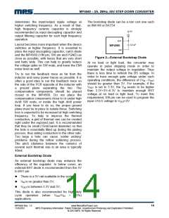
Output Rectifier Diode
Choose a diode whose maximum reverse voltage
rating is greater than the maximum input voltage,
and whose current rating is greater than the
maximum load current. Table 2 lists example
Schottky diodes and manufacturers.
The output rectifier diode supplies the current to
the inductor when the high-side switch is off. To
reduce losses due to the diode forward voltage
and recovery times, use a Schottky diode.
Table 2—Diode Selection Guide
Voltage/
Current
Rating
Diodes
Manufacturer
B290-13-F
B380-13-F
CMSH2-100M
CMSH3-100MA
90V, 2A
80V, 3A
100V, 2A
100V, 3A
Diodes Inc.
Diodes Inc.
Central Semi
Central Semi
MP4560 Rev. 1.0
11/5/2012
www.MonolithicPower.com
MPS Proprietary Information. Patent Protected. Unauthorized Photocopy and Duplication Prohibited.
© 2012 MPS. All Rights Reserved.
11

 MPS [ MONOLITHIC POWER SYSTEMS ]