MP1584 – 3A, 1.5MHz, 28V STEP-DOWN CONVERTER
APPLICATION INFORMATION
A good rule for determining the inductance to
use is to allow the peak-to-peak ripple current in
the inductor to be approximately 30% of the
maximum switch current limit. Also, make sure
that the peak inductor current is below the
maximum switch current limit. The inductance
value can be calculated by:
COMPONENT SELECTION
Setting the Output Voltage
The output voltage is set using a resistive
voltage divider from the output voltage to FB pin.
The voltage divider divides the output voltage
down to the feedback voltage by the
ratio:
R2
VOUT
V
OUT
VFB V
L1
1
OUT R1 R2
fS ΔIL
V
IN
Thus the output voltage is:
Where VOUT is the output voltage, VIN is the input
voltage, fS is the switching frequency, and ΔIL is
the peak-to-peak inductor ripple current.
(R1 R2)
VOUT VFB
R2
Choose an inductor that will not saturate under
the maximum inductor peak current. The peak
inductor current can be calculated by:
About 20µA current from high side BS circuitry
can be seen at the output when the MP1584 is
at no load. In order to absorb this small amount
of current, keep R2 under 40Kꢀ. A typical
value for R2 can be 40.2kꢀ. With this value, R1
can be determined by:
VOUT
V
OUT
ILP ILOAD
1
2 fS L1
V
IN
Where ILOAD is the load current.
R1 50.25 (VOUT 0.8)(k)
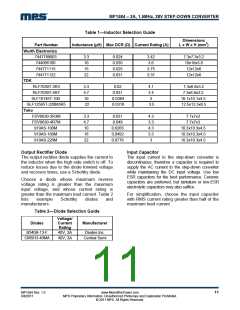
Table 1 lists a number of suitable inductors
from various manufacturers. The choice of
which style inductor to use mainly depends on
the price vs. size requirements and any EMI
requirement.
For example, for a 3.3V output voltage, R2 is
40.2kꢀ, and R1 is 127kꢀ.
Inductor
The inductor is required to supply constant
current to the output load while being driven by
the switched input voltage. A larger value
inductor will result in less ripple current that will
result in lower output ripple voltage. However,
the larger value inductor will have a larger
physical size, higher series resistance, and/or
lower saturation current.
MP1584 Rev. 1.0
8/8/2011
www.MonolithicPower.com
MPS Proprietary Information. Unauthorized Photocopy and Duplication Prohibited.
© 2011 MPS. All Rights Reserved.
10

 MPS [ MONOLITHIC POWER SYSTEMS ]